Adafruit · Dev board
Adafruit Feather (standard footprint)
Not one board: the footprint every Feather and FeatherWing shares, from the 32u4 to the RP2040 and ESP32-S3. USB at the top.
- Logic level
- 3.3 V, mandated by the specification
- Package
- 16-pin and 12-pin headers, 0.9 x 2.0 in
1.Pinout diagram
Highlight a signalhover to preview, click to keep
16-pin side (USB at top)
FEATHER
12-pin side (USB at top)
Pin detail
Hover a pin for its mappings and gotchas. Click to keep it here.
- Logic level
- 3.3 V, mandated by the specification
- Package
- 16-pin and 12-pin headers, 0.9 x 2.0 in
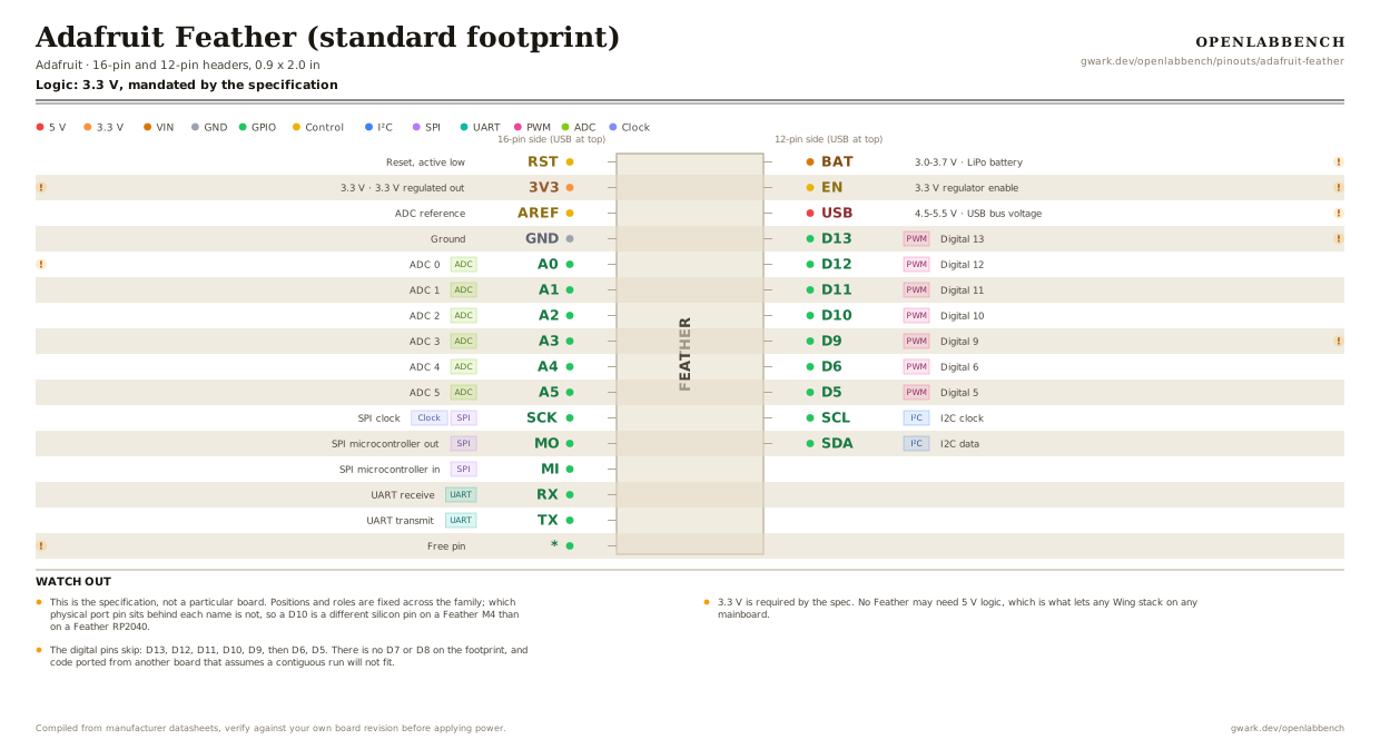
Fig. 1. Adafruit Feather (standard footprint), 16-pin and 12-pin headers, 0.9 x 2.0 in. Hover or tap a signal to light up every pin that carries it.
2.Watch out
- This is the specification, not a particular board. Positions and roles are fixed across the family; which physical port pin sits behind each name is not, so a D10 is a different silicon pin on a Feather M4 than on a Feather RP2040.
- 3.3 V is required by the spec. No Feather may need 5 V logic, which is what lets any Wing stack on any mainboard.
- The digital pins skip: D13, D12, D11, D10, D9, then D6, D5. There is no D7 or D8 on the footprint, and code ported from another board that assumes a contiguous run will not fit.
- Position 16 on the long side is a deliberate free pin. Every board puts something different there, so a Wing must not rely on it.
- BAT is a LiPo rail, not a generic input. The spec obliges every mainboard to include charging and a JST-PH connector, which is why Feathers are the usual choice for a battery project.
- EN pulls down to shut off the 3.3 V regulator, and only that. BAT and USB stay live, so it is a logic-off switch and not a power cut.
- A0 is commonly the DAC output on Feathers that have one, which is worth knowing before using it as a plain analog input.
- The QT Py and Seeed XIAO share a different, smaller 14-pin footprint. Feather Wings do not fit those.
3.Full pin reference
Every pin, alias and mapping. This is the table that prints.
Table 1. Pin assignments.
| Pin | Name | Also called | Functions | Notes |
|---|---|---|---|---|
| - | RST | Rst | Reset, active low | |
| - | 3V33.3 V | - | 3.3 V regulated out | Output to a FeatherWing, not an input. |
| - | AREF | Aref | ADC reference | |
| - | GND | - | Ground | |
| - | A0ADC | - | ADC 0 | Often the only true DAC output on Feathers that have one. |
| - | A1ADC | - | ADC 1 | |
| - | A2ADC | - | ADC 2 | |
| - | A3ADC | - | ADC 3 | |
| - | A4ADC | D24 | ADC 4 | |
| - | A5ADC | D25 | ADC 5 | |
| - | SCKSPIClock | - | SPI clock | |
| - | MOSPI | MOSI | SPI microcontroller out | |
| - | MISPI | MISO | SPI microcontroller in | |
| - | RXUART | D0 | UART receive | |
| - | TXUART | D1 | UART transmit | |
| - | * | - | Free pin | The one position the spec leaves open. What lands here differs on every Feather, so never assume it in a Wing. |
| - | BAT3.0-3.7 V | VBAT | LiPo battery | Every Feather mainboard has to carry LiPo charging and a JST-PH connector, so this is always a real battery rail. |
| - | EN | - | 3.3 V regulator enable | Pulled high through 100k. Pull low to kill the 3.3 V rail. It does not cut BAT or USB. |
| - | USB4.5-5.5 V | VBUS | USB bus voltage | About 500 mA, and only live when USB is plugged in. |
| - | D13PWM | - | Digital 13 | The on-board LED on essentially every Feather. |
| - | D12PWM | - | Digital 12 | |
| - | D11PWM | - | Digital 11 | |
| - | D10PWM | - | Digital 10 | |
| - | D9PWM | - | Digital 9 | The digital block jumps from D9 to D6. There is no D7 or D8 on the standard footprint. |
| - | D6PWM | - | Digital 6 | |
| - | D5PWM | - | Digital 5 | |
| - | SCLI²C | - | I2C clock | |
| - | SDAI²C | - | I2C data |
Looking for a substitute?
Primary sources
Found a wrong pin? The whole board is one file, data/boards/adafruit-feather.json.