Arduino · Dev board
Arduino Mega 2560 (main headers)
ATmega2560 with 54 digital pins, 16 analog inputs and four hardware serial ports. These are the Uno-compatible side headers; D22 to D53 live on the separate double-row header at the end of the board.
- Logic level
- 5 V
- Package
- Mega shield form factor, 101.5 x 53.3 mm
1.Pinout diagram
Highlight a signalhover to preview, click to keep
Power + Analog headers
MEGA 2560
Digital + Communication headers
Pin detail
Hover a pin for its mappings and gotchas. Click to keep it here.
- Logic level
- 5 V
- Package
- Mega shield form factor, 101.5 x 53.3 mm
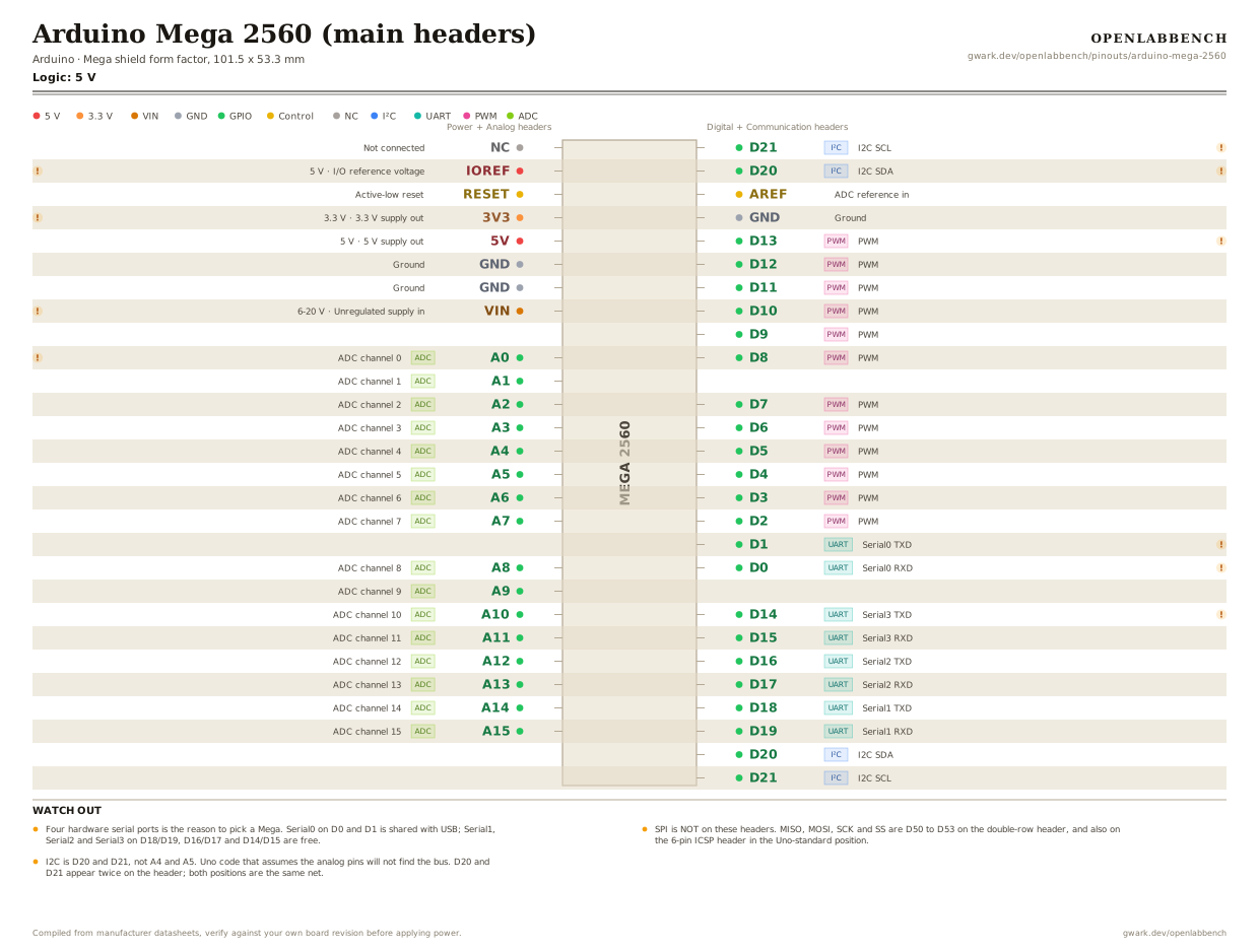
Fig. 1. Arduino Mega 2560 (main headers), Mega shield form factor, 101.5 x 53.3 mm. Hover or tap a signal to light up every pin that carries it.
2.Watch out
- Four hardware serial ports is the reason to pick a Mega. Serial0 on D0 and D1 is shared with USB; Serial1, Serial2 and Serial3 on D18/D19, D16/D17 and D14/D15 are free.
- SPI is NOT on these headers. MISO, MOSI, SCK and SS are D50 to D53 on the double-row header, and also on the 6-pin ICSP header in the Uno-standard position.
- I2C is D20 and D21, not A4 and A5. Uno code that assumes the analog pins will not find the bus. D20 and D21 appear twice on the header; both positions are the same net.
- PWM is available on D2 to D13 and on D44, D45 and D46, which are on the double-row header. Fifteen in total.
- The analog pins double as digital D54 to D69, so A0 is also pin 54 in code.
- 20 mA per I/O pin maximum and 50 mA total from the 3V3 pin, which comes from the USB bridge rather than a real regulator.
- VIN takes 6 to 20 V, with 7 to 12 V recommended. Above that the linear regulator cooks under any real load.
- This is the board inside most RAMPS-based 3D printers, which is why it stays in production long after an ESP32 would do the job for less.
3.Full pin reference
Every pin, alias and mapping. This is the table that prints.
Table 1. Pin assignments.
| Pin | Name | Also called | Functions | Notes |
|---|---|---|---|---|
| - | NC | - | Not connected | |
| - | IOREF5 V | - | I/O reference voltage | Tells a shield the board's logic level. |
| - | RESET | - | Active-low reset | |
| - | 3V33.3 V | - | 3.3 V supply out | 50 mA maximum, from the USB bridge regulator. |
| - | 5V5 V | - | 5 V supply out | |
| - | GND | - | Ground | |
| - | GND | - | Ground | |
| - | VIN6-20 V | - | Unregulated supply in | 7 to 12 V recommended. The barrel jack lands here. |
| - | A0ADC | D54, PF0, ADC0 | ADC channel 0 | The analog pins double as digital D54 to D69. |
| - | A1ADC | D55, PF1, ADC1 | ADC channel 1 | |
| - | A2ADC | D56, PF2, ADC2 | ADC channel 2 | |
| - | A3ADC | D57, PF3, ADC3 | ADC channel 3 | |
| - | A4ADC | D58, PF4, ADC4 | ADC channel 4 | |
| - | A5ADC | D59, PF5, ADC5 | ADC channel 5 | |
| - | A6ADC | D60, PF6, ADC6 | ADC channel 6 | |
| - | A7ADC | D61, PF7, ADC7 | ADC channel 7 | |
| - | A8ADC | D62, PK0, ADC8 | ADC channel 8 | |
| - | A9ADC | D63, PK1, ADC9 | ADC channel 9 | |
| - | A10ADC | D64, PK2, ADC10 | ADC channel 10 | |
| - | A11ADC | D65, PK3, ADC11 | ADC channel 11 | |
| - | A12ADC | D66, PK4, ADC12 | ADC channel 12 | |
| - | A13ADC | D67, PK5, ADC13 | ADC channel 13 | |
| - | A14ADC | D68, PK6, ADC14 | ADC channel 14 | |
| - | A15ADC | D69, PK7, ADC15 | ADC channel 15 | |
| - | D21I²C | SCL, PD0 | I2C SCL | Same net as D21 lower down the header. Duplicated for shield compatibility. |
| - | D20I²C | SDA, PD1 | I2C SDA | Same net as D20 lower down the header. |
| - | AREF | - | ADC reference in | |
| - | GND | - | Ground | |
| - | D13PWM | PB7 | PWM | D13 drives the on-board LED through a resistor. |
| - | D12PWM | PB6 | PWM | |
| - | D11PWM | PB5 | PWM | |
| - | D10PWM | PB4 | PWM | |
| - | D9PWM | PH6 | PWM | |
| - | D8PWM | PH5 | PWM | |
| - | D7PWM | PH4 | PWM | |
| - | D6PWM | PH3 | PWM | |
| - | D5PWM | PE3 | PWM | |
| - | D4PWM | PG5 | PWM | |
| - | D3PWM | PE5 | PWM | |
| - | D2PWM | PE4 | PWM | |
| - | D1UART | TX0, PE1 | Serial0 TXD | Shared with the USB bridge. |
| - | D0UART | RX0, PE0 | Serial0 RXD | Shared with the USB bridge. |
| - | D14UART | TX3, PJ1 | Serial3 TXD | Four hardware serial ports is the Mega's real advantage over an Uno. |
| - | D15UART | RX3, PJ0 | Serial3 RXD | |
| - | D16UART | TX2, PH1 | Serial2 TXD | |
| - | D17UART | RX2, PH0 | Serial2 RXD | |
| - | D18UART | TX1, PD3 | Serial1 TXD | |
| - | D19UART | RX1, PD2 | Serial1 RXD | |
| - | D20I²C | SDA, PD1 | I2C SDA | |
| - | D21I²C | SCL, PD0 | I2C SCL |
Found a wrong pin? The whole board is one file, data/boards/arduino-mega-2560.json.