BeagleBoard.org · Single-board computer
BeagleBone Black P8 Header
The GPIO side of the BeagleBone Black. Most of it is already spoken for by the on-board eMMC and HDMI, which is the first thing to work out before wiring a cape.
- Logic level
- 3.3 V
- Package
- 2x23 2.54 mm (P8)
1.Pinout diagram
Highlight a signalhover to preview, click to keep
Odd pins
BBB P8
Even pins
Pin detail
Hover a pin for its mappings and gotchas. Click to keep it here.
- Logic level
- 3.3 V
- Package
- 2x23 2.54 mm (P8)
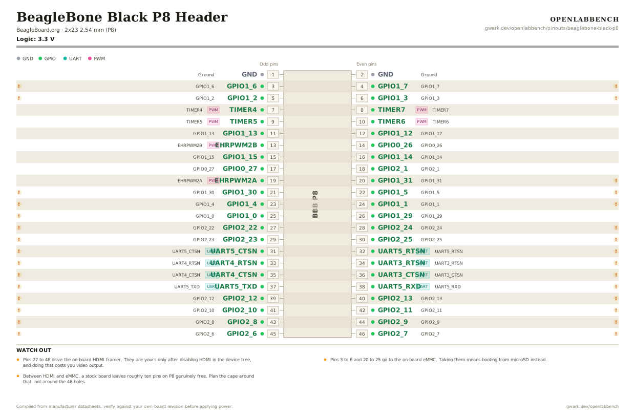
Fig. 1. BeagleBone Black P8 Header, 2x23 2.54 mm (P8). Hover or tap a signal to light up every pin that carries it.
2.Watch out
- Pins 27 to 46 drive the on-board HDMI framer. They are yours only after disabling HDMI in the device tree, and doing that costs you video output.
- Pins 3 to 6 and 20 to 25 go to the on-board eMMC. Taking them means booting from microSD instead.
- Between HDMI and eMMC, a stock board leaves roughly ten pins on P8 genuinely free. Plan the cape around that, not around the 46 holes.
- Signal names here are the power-on defaults. Nearly every pin muxes to something else, and several reach the PRU, the real reason to pick this board over a Pi.
- GPIO are 3.3 V and not 5 V tolerant, at 4 to 6 mA per pin.
- The P8 and P9 headers are keyed the same and sit the same distance apart as on the original BeagleBone, so older capes still fit.
- The other side of this board is the P9 header, documented separately: gwark.dev/openlabbench/pinouts/beaglebone-black-p9
3.Full pin reference
Every pin, alias and mapping. This is the table that prints.
Table 1. Pin assignments.
| Pin | Name | Also called | Functions | Notes |
|---|---|---|---|---|
| 1 | GND | - | Ground | |
| 2 | GND | - | Ground | |
| 3 | GPIO1_6 | R9 | GPIO1_6 | Wired to the on-board eMMC. Using it breaks eMMC boot. |
| 4 | GPIO1_7 | T9 | GPIO1_7 | Wired to the on-board eMMC. Using it breaks eMMC boot. |
| 5 | GPIO1_2 | R8 | GPIO1_2 | Wired to the on-board eMMC. Using it breaks eMMC boot. |
| 6 | GPIO1_3 | T8 | GPIO1_3 | Wired to the on-board eMMC. Using it breaks eMMC boot. |
| 7 | TIMER4PWM | R7 | TIMER4 | |
| 8 | TIMER7PWM | T7 | TIMER7 | |
| 9 | TIMER5PWM | T6 | TIMER5 | |
| 10 | TIMER6PWM | U6 | TIMER6 | |
| 11 | GPIO1_13 | R12 | GPIO1_13 | |
| 12 | GPIO1_12 | T12 | GPIO1_12 | |
| 13 | EHRPWM2BPWM | T10 | EHRPWM2B | |
| 14 | GPIO0_26 | T11 | GPIO0_26 | |
| 15 | GPIO1_15 | U13 | GPIO1_15 | |
| 16 | GPIO1_14 | V13 | GPIO1_14 | |
| 17 | GPIO0_27 | U12 | GPIO0_27 | |
| 18 | GPIO2_1 | V12 | GPIO2_1 | |
| 19 | EHRPWM2APWM | U10 | EHRPWM2A | |
| 20 | GPIO1_31 | V9 | GPIO1_31 | Wired to the on-board eMMC. Using it breaks eMMC boot. |
| 21 | GPIO1_30 | U9 | GPIO1_30 | Wired to the on-board eMMC. Using it breaks eMMC boot. |
| 22 | GPIO1_5 | V8 | GPIO1_5 | Wired to the on-board eMMC. Using it breaks eMMC boot. |
| 23 | GPIO1_4 | U8 | GPIO1_4 | Wired to the on-board eMMC. Using it breaks eMMC boot. |
| 24 | GPIO1_1 | V7 | GPIO1_1 | Wired to the on-board eMMC. Using it breaks eMMC boot. |
| 25 | GPIO1_0 | U7 | GPIO1_0 | Wired to the on-board eMMC. Using it breaks eMMC boot. |
| 26 | GPIO1_29 | V6 | GPIO1_29 | |
| 27 | GPIO2_22 | U5 | GPIO2_22 | Wired to the on-board HDMI framer. Free only once HDMI is disabled in the device tree. |
| 28 | GPIO2_24 | V5 | GPIO2_24 | Wired to the on-board HDMI framer. Free only once HDMI is disabled in the device tree. |
| 29 | GPIO2_23 | R5 | GPIO2_23 | Wired to the on-board HDMI framer. Free only once HDMI is disabled in the device tree. |
| 30 | GPIO2_25 | R6 | GPIO2_25 | Wired to the on-board HDMI framer. Free only once HDMI is disabled in the device tree. |
| 31 | UART5_CTSNUART | V4 | UART5_CTSN | Wired to the on-board HDMI framer. Free only once HDMI is disabled in the device tree. |
| 32 | UART5_RTSNUART | T5 | UART5_RTSN | Wired to the on-board HDMI framer. Free only once HDMI is disabled in the device tree. |
| 33 | UART4_RTSNUART | V3 | UART4_RTSN | Wired to the on-board HDMI framer. Free only once HDMI is disabled in the device tree. |
| 34 | UART3_RTSNUART | U4 | UART3_RTSN | Wired to the on-board HDMI framer. Free only once HDMI is disabled in the device tree. |
| 35 | UART4_CTSNUART | V2 | UART4_CTSN | Wired to the on-board HDMI framer. Free only once HDMI is disabled in the device tree. |
| 36 | UART3_CTSNUART | U3 | UART3_CTSN | Wired to the on-board HDMI framer. Free only once HDMI is disabled in the device tree. |
| 37 | UART5_TXDUART | U1 | UART5_TXD | Wired to the on-board HDMI framer. Free only once HDMI is disabled in the device tree. |
| 38 | UART5_RXDUART | U2 | UART5_RXD | Wired to the on-board HDMI framer. Free only once HDMI is disabled in the device tree. |
| 39 | GPIO2_12 | T3 | GPIO2_12 | Wired to the on-board HDMI framer. Free only once HDMI is disabled in the device tree. |
| 40 | GPIO2_13 | T4 | GPIO2_13 | Wired to the on-board HDMI framer. Free only once HDMI is disabled in the device tree. |
| 41 | GPIO2_10 | T1 | GPIO2_10 | Wired to the on-board HDMI framer. Free only once HDMI is disabled in the device tree. |
| 42 | GPIO2_11 | T2 | GPIO2_11 | Wired to the on-board HDMI framer. Free only once HDMI is disabled in the device tree. |
| 43 | GPIO2_8 | R3 | GPIO2_8 | Wired to the on-board HDMI framer. Free only once HDMI is disabled in the device tree. |
| 44 | GPIO2_9 | R4 | GPIO2_9 | Wired to the on-board HDMI framer. Free only once HDMI is disabled in the device tree. |
| 45 | GPIO2_6 | R1 | GPIO2_6 | Wired to the on-board HDMI framer. Free only once HDMI is disabled in the device tree. |
| 46 | GPIO2_7 | R2 | GPIO2_7 | Wired to the on-board HDMI framer. Free only once HDMI is disabled in the device tree. |
Found a wrong pin? The whole board is one file, data/boards/beaglebone-black-p8.json.