Bosch Sensortec · Integrated circuit
BME280 Humidity, Pressure and Temperature Sensor
Three environmental measurements in a grain of rice, over I2C or SPI. Accurate enough on pressure to tell which floor of a building you are on.
- Logic level
- 1.71-3.6 V
- Package
- LGA-8, 2.5 x 2.5 mm
1.Pinout diagram
Highlight a signalhover to preview, click to keep
Pins 1-4
Pins 5-8
Pin detail
Hover a pin for its mappings and gotchas. Click to keep it here.
- Logic level
- 1.71-3.6 V
- Package
- LGA-8, 2.5 x 2.5 mm
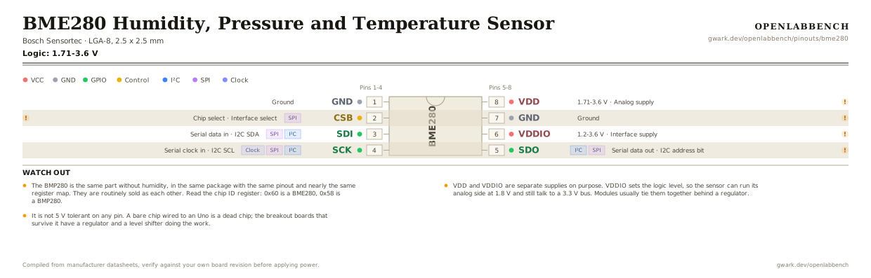
Fig. 1. BME280 Humidity, Pressure and Temperature Sensor, LGA-8, 2.5 x 2.5 mm. Hover or tap a signal to light up every pin that carries it.
2.Watch out
- The BMP280 is the same part without humidity, in the same package with the same pinout and nearly the same register map. They are routinely sold as each other. Read the chip ID register: 0x60 is a BME280, 0x58 is a BMP280.
- VDD and VDDIO are separate supplies on purpose. VDDIO sets the logic level, so the sensor can run its analog side at 1.8 V and still talk to a 3.3 V bus. Modules usually tie them together behind a regulator.
- It is not 5 V tolerant on any pin. A bare chip wired to an Uno is a dead chip; the breakout boards that survive it have a regulator and a level shifter doing the work.
- CSB picks the interface, and it is sampled rather than strapped: tie it to VDDIO for I2C, or drive it as chip select for SPI. Left floating it will not reliably be either.
- SDO is the address bit in I2C mode. Low gives 0x76 and high gives 0x77, and it must be driven, not left open. Two sensors on one bus is the most this part will do.
- The temperature reading is the die's own, and the die sits next to a thing you are powering. Forced mode, one reading at a time with the chip asleep in between, reports ambient. Continuous mode at a high rate reports the chip warming itself up, usually by a degree or two.
- Pressure comes out in Pa with a 20-bit resolution, and the compensation routine in the datasheet is not optional: the raw value is meaningless without the per-chip calibration coefficients read out of registers 0x88 onward.
- The pin table here is the chip's own, as numbered by Bosch. The real package is a square LGA with pads on all four sides, so these are the datasheet's numbers rather than a shape you can read off the part.
3.Minimum circuit on I2C
What has to go around the chip before it will run.
| Part | Between | Why |
|---|---|---|
| 100 nF ceramic | VDD (8) to GND | Analog supply decoupling. The pressure reading is a 20-bit measurement against this rail. |
| 100 nF ceramic | VDDIO (6) to GND | Interface supply decoupling. VDDIO is a separate rail and needs its own capacitor. |
| Interface link | CSB (2) to VCC | CSB to VDDIO selects I2C. For SPI this pin becomes chip select instead, driven by the controller. |
| Address link | SDO (5) to GND | SDO low sets the address to 0x76. High gives 0x77. It has to be driven either way. |
| 4.7 kOhm | SDI (3) to VCC | I2C pull-up on SDA, which is the SDI pin in I2C mode. |
| 4.7 kOhm | SCK (4) to VCC | I2C pull-up on SCL, which is the SCK pin in I2C mode. One pair per bus. |
Both ground pins must be connected. For SPI, leave the pull-ups off and treat SDI as MOSI, SDO as MISO, SCK as clock and CSB as chip select.
4.Full pin reference
Every pin, alias and mapping. This is the table that prints.
Table 2. Pin assignments.
| Pin | Name | Also called | Functions | Notes |
|---|---|---|---|---|
| 1 | GND | - | Ground | |
| 2 | CSBSPI | - | Chip select, Interface select | To VDDIO for I2C. Driven low as chip select for SPI. |
| 3 | SDII²CSPI | SDA, MOSI | Serial data in, I2C SDA | |
| 4 | SCKI²CSPIClock | SCL | Serial clock in, I2C SCL | |
| 5 | SDOI²CSPI | MISO | Serial data out, I2C address bit | Low is 0x76, high is 0x77. Not connected in 3-wire SPI. |
| 6 | VDDIO1.2-3.6 V | - | Interface supply | Sets the logic level, independently of VDD. |
| 7 | GND | - | Ground | Both ground pins have to be connected. |
| 8 | VDD1.71-3.6 V | - | Analog supply | Not 5 V tolerant. Nothing on this part is. |
Looking for a substitute?
Primary sources
Found a wrong pin? The whole board is one file, data/boards/bme280.json.