TI / ON / many · Integrated circuit
CD4017 Decade Counter
Ten outputs, one high at a time, advancing on each clock. Pair it with a 555 and you have a chaser with no code at all.
- Logic level
- 3-18 V (CMOS)
- Package
- PDIP-16 / SOIC-16
1.Pinout diagram
Highlight a signalhover to preview, click to keep
Pins 1-8
CD4017
Pins 9-16
Pin detail
Hover a pin for its mappings and gotchas. Click to keep it here.
- Logic level
- 3-18 V (CMOS)
- Package
- PDIP-16 / SOIC-16
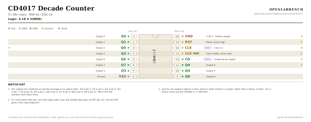
Fig. 1. CD4017 Decade Counter, PDIP-16. Hover or tap a signal to light up every pin that carries it.
2.Watch out
- The outputs are scattered across the package in no useful order: Q0 is pin 3, Q1 is pin 2, Q2 is pin 4, Q3 is pin 7, Q4 is pin 10, Q5 is pin 1, Q6 is pin 5, Q7 is pin 6, Q8 is pin 9, Q9 is pin 11. Wire from the numbers and check twice.
- Exactly one output is high at a time, which is what makes it a chaser rather than a binary counter. For a binary count use the CD4024 or a 74HC393.
- To count fewer than ten, wire the output after your last wanted step back to RST (pin 15). Q4 into RST gives a four-step sequence.
- RST (15) and CLK INH (13) must both be grounded for normal counting. Leaving either floating is why a breadboarded 4017 sits still or counts randomly.
- CO (pin 12) goes high for counts 0 to 4 and low for 5 to 9, so it is a divide-by-ten output for chaining a second chip.
- It runs from 3 to 18 V, which is the real reason to reach for CMOS 4000-series over 74HC here. Output drive is weak, a few mA, so LEDs want a transistor above about 5 mA.
3.Minimum circuit
What has to go around the chip before it will run.
| Part | Between | Why |
|---|---|---|
| Wire link | RST (15) to GND | Reset is active high. Floating, the counter restarts at random and looks like it is skipping steps. |
| Wire link | CLK INH (13) to GND | Clock inhibit is active high too. Left floating the counter may simply never advance. |
| 100 nF | VDD (16) to GND | Supply decoupling at the pin. |
Drive the clock from something with clean edges. A slow or noisy edge counts several times, which is why a 4017 fed straight from a button jumps three or four outputs per press.
4.Full pin reference
Every pin, alias and mapping. This is the table that prints.
Table 2. Pin assignments.
| Pin | Name | Also called | Functions | Notes |
|---|---|---|---|---|
| 1 | Q5 | - | Output 5 | |
| 2 | Q1 | - | Output 1 | |
| 3 | Q0 | - | Output 0 | High at reset and on the first count. |
| 4 | Q2 | - | Output 2 | |
| 5 | Q6 | - | Output 6 | |
| 6 | Q7 | - | Output 7 | |
| 7 | Q3 | - | Output 3 | |
| 8 | VSS | GND | Ground | |
| 9 | Q8 | - | Output 8 | |
| 10 | Q4 | - | Output 4 | |
| 11 | Q9 | - | Output 9 | Wire this to RST for a nine-step sequence, or any earlier output for a shorter one. |
| 12 | COClock | CARRY OUT, Q5-9 | Divide-by-ten output | Feeds the clock of the next 4017 when chaining. |
| 13 | CLK INH | CE | Clock inhibit, active high | Ground it for normal counting. |
| 14 | CLKClock | - | Clock in | Counts on the rising edge. Needs a clean edge; a slow RC ramp makes it skip. |
| 15 | RST | MR, RESET | Reset, active high | Ground it for normal counting. High forces Q0. |
| 16 | VDD3-18 V | - | Positive supply | 100 nF to GND at the pin. |
Looking for a substitute?
Primary sources
Found a wrong pin? The whole board is one file, data/boards/cd4017.json.