Aosong · Integrated circuit
DHT22 / AM2302 Humidity and Temperature Sensor
Humidity and temperature on one wire, in a plastic grille you can read in about ten lines of code. Slow, cheap and everywhere.
- Logic level
- 3.3-5.5 V
- Package
- 4-pin single row, 2.54 mm
1.Pinout diagram
Highlight a signalhover to preview, click to keep
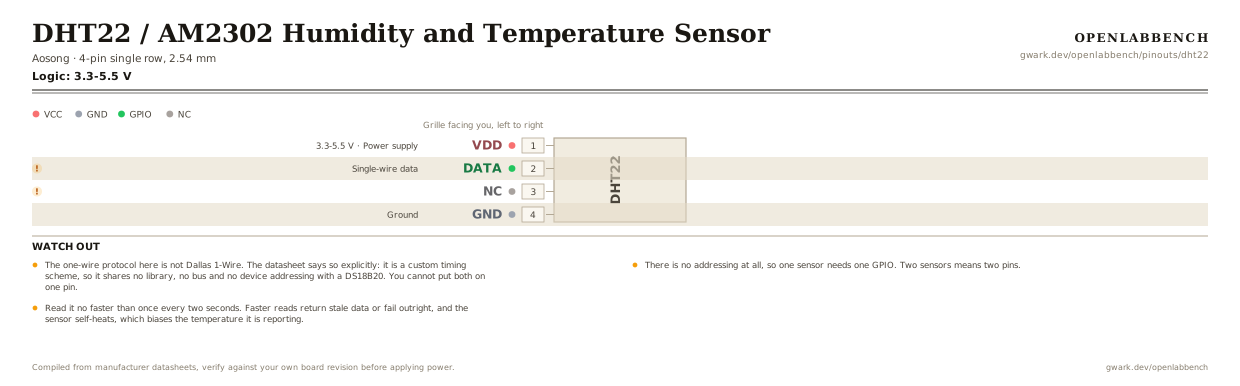
Grille facing you, left to right
DHT22
Pin detail
Hover a pin for its mappings and gotchas. Click to keep it here.
- Logic level
- 3.3-5.5 V
- Package
- 4-pin single row, 2.54 mm
Fig. 1. DHT22 / AM2302 Humidity and Temperature Sensor, 4-pin single row, 2.54 mm. Hover or tap a signal to light up every pin that carries it.
2.Watch out
- The one-wire protocol here is not Dallas 1-Wire. The datasheet says so explicitly: it is a custom timing scheme, so it shares no library, no bus and no device addressing with a DS18B20. You cannot put both on one pin.
- There is no addressing at all, so one sensor needs one GPIO. Two sensors means two pins.
- Read it no faster than once every two seconds. Faster reads return stale data or fail outright, and the sensor self-heats, which biases the temperature it is reporting.
- After power-up, wait a second before talking to it. The datasheet asks for this directly, and a read inside that window is the usual cause of a sensor that works only after a reset.
- The manufacturer's own connection diagram uses a 1 kOhm pull-up on the data line, not the 4.7 kOhm that most guides repeat. Either works over a short lead; the lower value is the one the maker drew.
- Pin 3 is not connected. The datasheet's pin table lists it struck through, left from a revision where it was a second ground. Leave it alone.
- The timing is tight enough that reads fail on a busy processor with interrupts running. That is the sensor's fault, not yours, and it is why most libraries disable interrupts for the duration of a read.
- The DHT11 is the same shape and protocol with worse everything: 1 percent humidity resolution against 0.1, and no negative temperatures. The AM2302 is the DHT22 with a cable instead of pins, red to power, black to ground, yellow to data.
3.Minimum circuit
What has to go around the chip before it will run.
| Part | Between | Why |
|---|---|---|
| 1 kOhm | DATA (2) to VCC | Pull-up on the data line, the value the manufacturer's own connection diagram uses. The line idles high and both ends pull it low to talk. |
| 100 nF ceramicoptional | VDD (1) to GND | Supply filtering between VDD and GND, suggested by the datasheet for wave filtering rather than required to function. |
That is the whole circuit. Data goes to any GPIO, and the sensor needs a second between power-up and the first read.
4.Full pin reference
Every pin, alias and mapping. This is the table that prints.
Table 2. Pin assignments.
| Pin | Name | Also called | Functions | Notes |
|---|---|---|---|---|
| 1 | VDD3.3-5.5 V | - | Power supply | |
| 2 | DATA | - | Single-wire data | Needs a pull-up. Not compatible with Dallas 1-Wire. |
| 3 | NC | - | - | Struck through in the datasheet's table. A second ground on an older revision. |
| 4 | GND | - | Ground |
Looking for a substitute?
Primary sources
Found a wrong pin? The whole board is one file, data/boards/dht22.json.