Analog Devices (Maxim) · Integrated circuit
DS1307 Real-Time Clock
The cheap I2C clock chip. Keeps time on a coin cell for years and drifts minutes a month, because the crystal is bare and uncompensated.
- Logic level
- 4.5-5.5 V
- Package
- PDIP-8 / SOIC-8
1.Pinout diagram
Highlight a signalhover to preview, click to keep
Pins 1-4
DS1307
Pins 5-8
Pin detail
Hover a pin for its mappings and gotchas. Click to keep it here.
- Logic level
- 4.5-5.5 V
- Package
- PDIP-8 / SOIC-8
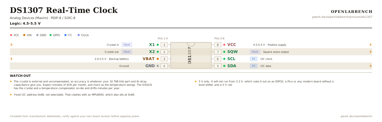
Fig. 1. DS1307 Real-Time Clock, PDIP-8. Hover or tap a signal to light up every pin that carries it.
2.Watch out
- The crystal is external and uncompensated, so accuracy is whatever your 32.768 kHz part and its stray capacitance give you. Expect minutes of drift per month, and more as the temperature swings. The DS3231 has the crystal and a temperature compensator on-die and drifts minutes per year.
- 5 V only. It will not run from 3.3 V, which rules it out on an ESP32, a Pico or any modern board without a level shifter and a 5 V rail.
- Fixed I2C address 0x68, not selectable. That clashes with an MPU6050, which also sits at 0x68.
- The crystal must be a 32.768 kHz part with 12.5 pF load capacitance, mounted as close to pins 1 and 2 as possible, with no ground pour underneath. Stray capacitance here is the main reason a hand-built DS1307 runs fast or slow.
- SQW/OUT is open drain and can emit 1 Hz, 4.096 kHz, 8.192 kHz or 32.768 kHz, which makes a free interrupt tick. It needs a pull-up.
- There are 56 bytes of battery-backed RAM above the clock registers, which is handy for storing a few settings.
- On power-up the clock halt bit is set and the chip is NOT running. Clear bit 7 of register 0 or it sits there reading the same time forever, which is the usual first-time confusion.
3.Minimum circuit
What has to go around the chip before it will run.
| Part | Between | Why |
|---|---|---|
| 32.768 kHz crystal | X1 (1) to X2 (2) | 12.5 pF load type. Keep the traces short and any ground pour away from them. |
| CR2032 cell | VBAT (3) to GND | Keeps time with the supply off. Tie VBAT to ground if you fit no cell, never leave it floating. |
| 4.7 kOhm | SDA (5) to VCC | I2C data is open drain and the bus has no internal pull-ups. |
| 4.7 kOhm | SCL (6) to VCC | The matching pull-up for the clock line. |
| 100 nF | VCC (8) to GND | Supply decoupling at the pin. |
Stray capacitance around the crystal is the main reason a hand-built DS1307 runs fast or slow. The DS3231 puts the crystal on-die and avoids the problem.
4.Full pin reference
Every pin, alias and mapping. This is the table that prints.
Table 2. Pin assignments.
| Pin | Name | Also called | Functions | Notes |
|---|---|---|---|---|
| 1 | X1Clock | - | Crystal in | 32.768 kHz, 12.5 pF load. Keep the traces short and the ground pour away. |
| 2 | X2Clock | - | Crystal out | |
| 3 | VBAT2.0-3.5 V | - | Backup battery | A CR2032 lasts years. Tie to ground if unused, never leave floating. |
| 4 | GND | - | Ground | |
| 5 | SDAI²C | - | I2C data | Open drain. Needs a bus pull-up. |
| 6 | SCLI²C | - | I2C clock | |
| 7 | SQWClock | SQW/OUT | Square wave output | Open drain. 1 Hz, 4.096 kHz, 8.192 kHz or 32.768 kHz. Needs a pull-up. |
| 8 | VCC4.5-5.5 V | - | Positive supply | 5 V only. Below about 4.25 V it switches to the battery and stops answering on I2C. |
Found a wrong pin? The whole board is one file, data/boards/ds1307.json.