Analog Devices (Maxim) · Integrated circuit
DS18B20 Temperature Sensor
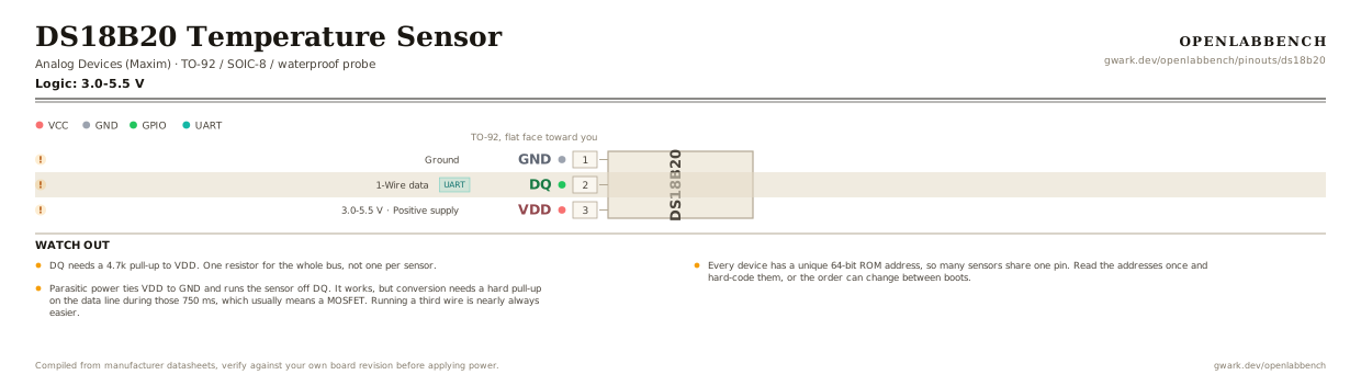
1-Wire digital thermometer. Dozens share a single microcontroller pin, each with its own 64-bit address. Flat face toward you, pins down.
- Logic level
- 3.0-5.5 V
- Package
- TO-92 / SOIC-8 / waterproof probe
1.Pinout diagram
Highlight a signalhover to preview, click to keep
TO-92, flat face toward you
Pin detail
Hover a pin for its mappings and gotchas. Click to keep it here.
- Logic level
- 3.0-5.5 V
- Package
- TO-92 / SOIC-8 / waterproof probe
Fig. 1. DS18B20 Temperature Sensor, TO-92. Hover or tap a signal to light up every pin that carries it.
2.Watch out
- DQ needs a 4.7k pull-up to VDD. One resistor for the whole bus, not one per sensor.
- Every device has a unique 64-bit ROM address, so many sensors share one pin. Read the addresses once and hard-code them, or the order can change between boots.
- Parasitic power ties VDD to GND and runs the sensor off DQ. It works, but conversion needs a hard pull-up on the data line during those 750 ms, which usually means a MOSFET. Running a third wire is nearly always easier.
- A 12-bit conversion takes up to 750 ms. Asking for the value immediately after requesting it returns the previous reading, which looks like lag that tracks your loop rate.
- Counterfeits are everywhere, especially in cheap waterproof probes. They typically fail at the extremes, ignore the resolution setting, or report in 0.5 degree steps. If readings look quantized, that is why.
- Rated minus 55 to 125 C, but the waterproof probes are only good to about 100 C because of the cable and the potting.
- On a Raspberry Pi the w1-gpio overlay expects GPIO4, pin 7 on the header.
3.1-Wire bus
What has to go around the chip before it will run.
| Part | Between | Why |
|---|---|---|
| 4.7 kOhm | DQ (2) to VDD (3) | One pull-up for the whole bus, not one per sensor. |
In parasitic power mode VDD ties to GND and the sensor runs off DQ, but conversion then needs a hard pull-up on the data line, usually a MOSFET. A third wire is easier.
4.Full pin reference
Every pin, alias and mapping. This is the table that prints.
Table 2. Pin assignments.
| Pin | Name | Also called | Functions | Notes |
|---|---|---|---|---|
| 1 | GND | - | Ground | Leftmost with the flat face toward you. |
| 2 | DQUART | - | 1-Wire data | Open drain. One 4.7k pull-up to VDD for the whole bus. |
| 3 | VDD3.0-5.5 V | - | Positive supply | Tie to GND for parasitic power, which then needs a strong pull-up on DQ during conversion. |
Looking for a substitute?
Primary sources
Found a wrong pin? The whole board is one file, data/boards/ds18b20.json.