Ai-Thinker · Dev board
ESP-01 / ESP-01S (ESP8266)
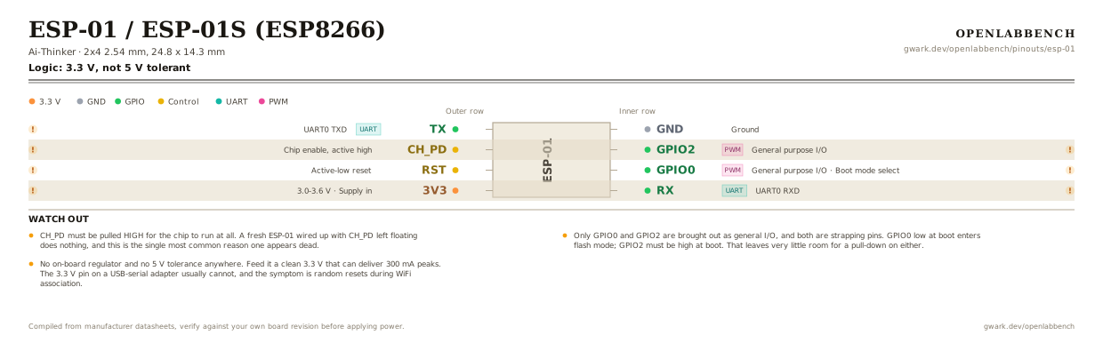
The cheapest way to put WiFi on something, and the most awkward. Two usable GPIO, both strapping pins, and no on-board regulator. Orientation below has the antenna on the right.
- Logic level
- 3.3 V, not 5 V tolerant
- Package
- 2x4 2.54 mm, 24.8 x 14.3 mm
1.Pinout diagram
Highlight a signalhover to preview, click to keep
Outer row
ESP-01
Inner row
Pin detail
Hover a pin for its mappings and gotchas. Click to keep it here.
- Logic level
- 3.3 V, not 5 V tolerant
- Package
- 2x4 2.54 mm, 24.8 x 14.3 mm
Fig. 1. ESP-01 / ESP-01S (ESP8266), 2x4 2.54 mm, 24.8 x 14.3 mm. Hover or tap a signal to light up every pin that carries it.
2.Watch out
- CH_PD must be pulled HIGH for the chip to run at all. A fresh ESP-01 wired up with CH_PD left floating does nothing, and this is the single most common reason one appears dead.
- Only GPIO0 and GPIO2 are brought out as general I/O, and both are strapping pins. GPIO0 low at boot enters flash mode; GPIO2 must be high at boot. That leaves very little room for a pull-down on either.
- No on-board regulator and no 5 V tolerance anywhere. Feed it a clean 3.3 V that can deliver 300 mA peaks. The 3.3 V pin on a USB-serial adapter usually cannot, and the symptom is random resets during WiFi association.
- TX and RX are 3.3 V. The module's RX is not 5 V tolerant, so a 5 V Arduino needs a divider on that line.
- No ADC pin is brought out, and neither is GPIO15 or GPIO16, so deep-sleep wake is not possible without soldering to the chip.
- The ESP-01S has 1 MB flash and moves the on-board LED to GPIO2. The original blue ESP-01 has 512 KB and its LED on the TX pin.
- The 2x4 header is on 2.54 mm pitch but the two rows are only 0.1 inch apart, so it does not straddle a breadboard center channel. Use an adapter or jumpers.
3.Full pin reference
Every pin, alias and mapping. This is the table that prints.
Table 1. Pin assignments.
| Pin | Name | Also called | Functions | Notes |
|---|---|---|---|---|
| - | TXUART | GPIO1, TXD0 | UART0 TXD | Also the boot log output. High at boot; pulling it low stops the chip starting. |
| - | CH_PD | CH_EN, EN | Chip enable, active high | Must be tied high, through 10k to 3.3 V. Nothing runs until it is. |
| - | RST | RESET | Active-low reset | Pull low to reset. Leave floating or pull high in normal use. |
| - | 3V33.0-3.6 V | - | Supply in | Supply input, not an output. Needs 300 mA of headroom for transmit bursts. |
| - | GND | - | Ground | |
| - | GPIO2PWM | LED on ESP-01S | General purpose I/O | Strapping pin: must be high at boot. Has an internal pull-up. One of only two usable I/O. |
| - | GPIO0PWM | FLASH | General purpose I/O, Boot mode select | Strapping pin: low at boot enters flash mode. A button to ground here is fine, a steady load is not. |
| - | RXUART | GPIO3, RXD0 | UART0 RXD | Not 5 V tolerant. A 5 V Arduino TX needs a divider into this pin. |
Looking for a substitute?
Primary sources
Found a wrong pin? The whole board is one file, data/boards/esp-01.json.