Generic · Integrated circuit
HC-SR04 Ultrasonic Rangefinder
Ping-and-listen distance sensor, 2 cm to 4 m. Four pins, 5 V only, and an echo pin that will happily feed 5 V into a 3.3 V board.
- Logic level
- 5 V
- Package
- 4-pin 2.54 mm header
1.Pinout diagram
Highlight a signalhover to preview, click to keep
Header, front view
Pin detail
Hover a pin for its mappings and gotchas. Click to keep it here.
- Logic level
- 5 V
- Package
- 4-pin 2.54 mm header
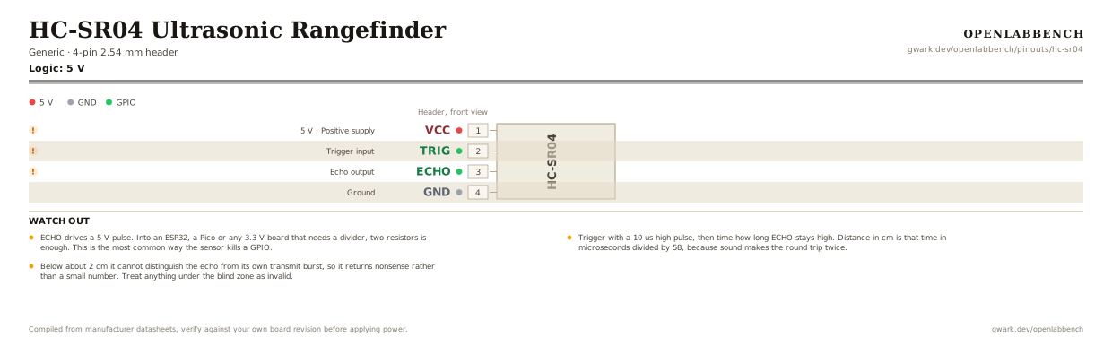
Fig. 1. HC-SR04 Ultrasonic Rangefinder, 4-pin 2.54 mm header. Hover or tap a signal to light up every pin that carries it.
2.Watch out
- ECHO drives a 5 V pulse. Into an ESP32, a Pico or any 3.3 V board that needs a divider, two resistors is enough. This is the most common way the sensor kills a GPIO.
- Trigger with a 10 us high pulse, then time how long ECHO stays high. Distance in cm is that time in microseconds divided by 58, because sound makes the round trip twice.
- Below about 2 cm it cannot distinguish the echo from its own transmit burst, so it returns nonsense rather than a small number. Treat anything under the blind zone as invalid.
- It needs a reasonably flat target square to the sensor. Soft, angled or narrow objects scatter the ping and read as out of range.
- If ECHO never goes low because nothing came back, a naive pulseIn blocks. Always use a timeout.
- The HC-SR04P and the RCWL-1601 are pin-compatible and run from 3 to 5.5 V, which removes the level shifting problem entirely. Worth buying instead.
- Readings drift with temperature: the speed of sound changes about 0.17 percent per degree C. Over a 30 degree swing that is a few centimetres at 4 m.
3.Level shifting the echo
What has to go around the chip before it will run.
| Part | Between | Why |
|---|---|---|
| 1 kOhm | ECHO (3) to MCU | In series with the 5 V echo output, the top half of a divider into a 3.3 V input. |
| 2 kOhm | MCU to GND | The lower half. 5 V across 1k and 2k puts 3.3 V on the junction, which is what the input sees. |
| 100 uFoptional | VCC (1) to GND | Across the supply at the module. Each ping pulls a 15 mA burst and a long thin lead sags under it. |
TRIG is an input and tolerates a 3.3 V drive, so only ECHO needs the divider. The module has no 3.3 V variant worth trusting: the ones sold as 3 V parts are usually the same board with a different regulator.
4.Full pin reference
Every pin, alias and mapping. This is the table that prints.
Table 2. Pin assignments.
| Pin | Name | Also called | Functions | Notes |
|---|---|---|---|---|
| 1 | VCC5 V | - | Positive supply | 5 V. The sensor draws a 15 mA burst on each ping. |
| 2 | TRIG | - | Trigger input | 10 us high pulse starts a measurement. |
| 3 | ECHO | - | Echo output | Outputs 5 V. Divide it down for a 3.3 V board. |
| 4 | GND | - | Ground |
Primary sources
Found a wrong pin? The whole board is one file, data/boards/hc-sr04.json.