Texas Instruments / STMicroelectronics · Integrated circuit
L293D Motor Driver
Quad half-bridge with built-in flyback diodes: two DC motors bidirectionally, or one bipolar stepper. Old, inefficient and still the part in every starter kit.
- Logic level
- 4.5-7 V logic / ≤36 V motor
- Package
- PDIP-16 / SOIC-16 (PowerDIP with fused GND)
1.Pinout diagram
Highlight a signalhover to preview, click to keep
Pins 1-8
Pins 9-16
Pin detail
Hover a pin for its mappings and gotchas. Click to keep it here.
- Logic level
- 4.5-7 V logic / ≤36 V motor
- Package
- PDIP-16 / SOIC-16 (PowerDIP with fused GND)
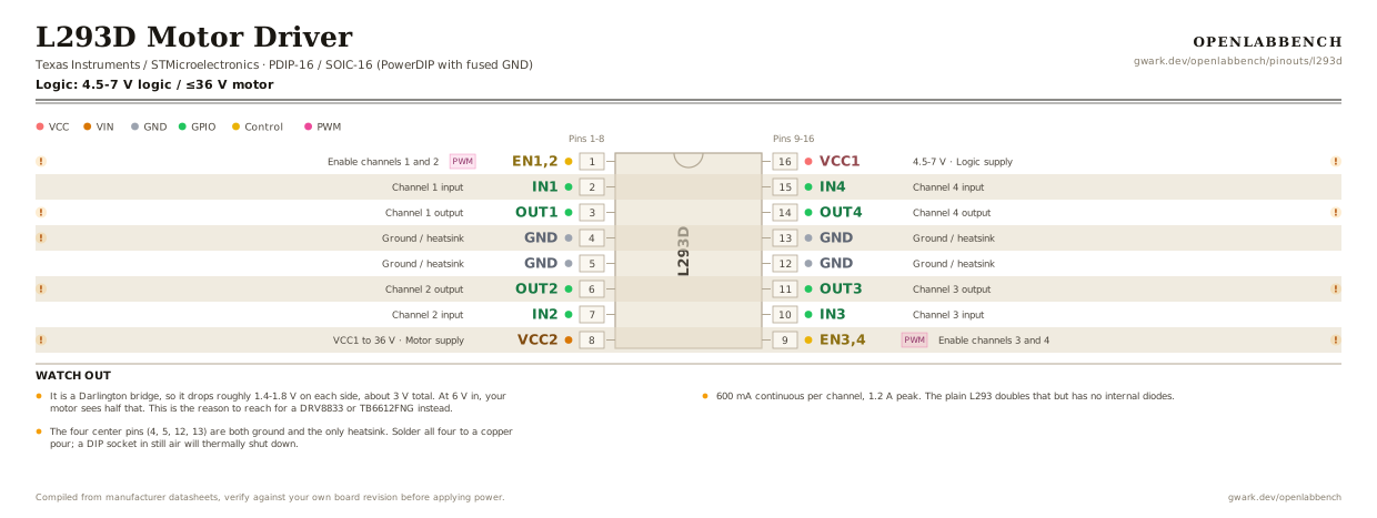
Fig. 1. L293D Motor Driver, PDIP-16. Hover or tap a signal to light up every pin that carries it.
2.Watch out
- It is a Darlington bridge, so it drops roughly 1.4-1.8 V on each side, about 3 V total. At 6 V in, your motor sees half that. This is the reason to reach for a DRV8833 or TB6612FNG instead.
- 600 mA continuous per channel, 1.2 A peak. The plain L293 doubles that but has no internal diodes.
- The four center pins (4, 5, 12, 13) are both ground and the only heatsink. Solder all four to a copper pour; a DIP socket in still air will thermally shut down.
- VCC1 (16) is logic and VCC2 (8) is the motor rail. Both are required, and VCC2 must be at or above VCC1.
- The two enable pins take PWM for speed control. PWM on the direction inputs instead works but is noisier and gives a worse low-speed response.
- The D in L293D means the clamp diodes are on-die. With a bare L293 you must add eight external Schottkys.
3.Driving one motor
What has to go around the chip before it will run.
| Part | Between | Why |
|---|---|---|
| Wire link | VCC1 (16) to VCC | Logic supply, 4.5 to 7 V. Separate from the motor rail and it must be powered first. |
| Wire link | VCC2 (8) to VM | Motor supply, up to 36 V. Tying it to the logic rail only works if the motor runs on 5 V. |
| 100 nF | VCC1 (16) to GND | Decoupling on the logic supply at the pin. |
| 100 uF | VCC2 (8) to GND | Bulk on the motor supply. Stall current comes from here, not from the logic rail. |
| Motor | OUT1 (3) to OUT2 (6) | A brushed motor across one half bridge. IN1 and IN2 set direction, EN1,2 gates both outputs. |
| Wire linkoptional | EN1,2 (1) to VCC | Enable tied high runs the bridge continuously. Drive it with PWM instead to control speed. |
The D suffix is the whole difference: the L293D has the clamp diodes on-die, the plain L293 does not and needs eight external ones. Both drop about 2 V across the output stage, so a 12 V motor on a 12 V rail sees closer to 10 V.
4.Full pin reference
Every pin, alias and mapping. This is the table that prints.
Table 2. Pin assignments.
| Pin | Name | Also called | Functions | Notes |
|---|---|---|---|---|
| 1 | EN1,2PWM | 1,2EN, ENA | Enable channels 1 and 2 | High to drive. PWM here for speed control on motor A. |
| 2 | IN1 | 1A | Channel 1 input | |
| 3 | OUT1 | 1Y | Channel 1 output | Motor A terminal. |
| 4 | GND | - | Ground / heatsink | One of four fused ground pins, the package's entire thermal path. |
| 5 | GND | - | Ground / heatsink | |
| 6 | OUT2 | 2Y | Channel 2 output | Motor A terminal. |
| 7 | IN2 | 2A | Channel 2 input | |
| 8 | VCC2VCC1 to 36 V | - | Motor supply | Needs a bulk electrolytic close by; motor current comes from here, not from your 5 V rail. |
| 9 | EN3,4PWM | 3,4EN, ENB | Enable channels 3 and 4 | PWM here for speed control on motor B. |
| 10 | IN3 | 3A | Channel 3 input | |
| 11 | OUT3 | 3Y | Channel 3 output | Motor B terminal. |
| 12 | GND | - | Ground / heatsink | |
| 13 | GND | - | Ground / heatsink | |
| 14 | OUT4 | 4Y | Channel 4 output | Motor B terminal. |
| 15 | IN4 | 4A | Channel 4 input | |
| 16 | VCC14.5-7 V | - | Logic supply | Separate from the motor rail. 100 nF at the pin. |
Looking for a substitute?
Primary sources
Found a wrong pin? The whole board is one file, data/boards/l293d.json.