TI / ON / many · Integrated circuit
LM339 Quad Comparator
Four open-collector comparators. Same package as the LM324 quad op-amp, but a different pinout.
- Logic level
- 2-36 V single or +/-1-18 V split
- Package
- PDIP-14 / SOIC-14
1.Pinout diagram
Highlight a signalhover to preview, click to keep
Pins 1-7
LM339
Pins 8-14
Pin detail
Hover a pin for its mappings and gotchas. Click to keep it here.
- Logic level
- 2-36 V single or +/-1-18 V split
- Package
- PDIP-14 / SOIC-14
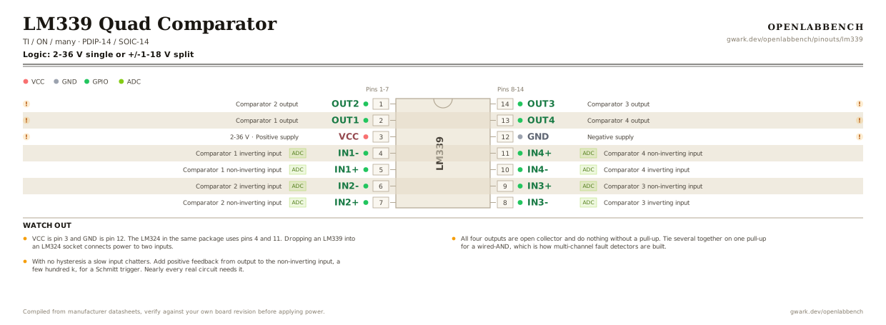
Fig. 1. LM339 Quad Comparator, PDIP-14. Hover or tap a signal to light up every pin that carries it.
2.Watch out
- VCC is pin 3 and GND is pin 12. The LM324 in the same package uses pins 4 and 11. Dropping an LM339 into an LM324 socket connects power to two inputs.
- All four outputs are open collector and do nothing without a pull-up. Tie several together on one pull-up for a wired-AND, which is how multi-channel fault detectors are built.
- With no hysteresis a slow input chatters. Add positive feedback from output to the non-inverting input, a few hundred k, for a Schmitt trigger. Nearly every real circuit needs it.
- Two comparators plus one AND gate gives you a window comparator, which is the classic use for a quad part.
- Input common mode goes to ground but stops about 1.5 V below V+, same as the LM393 and LM324.
- The LM393 is two of these in a DIP-8 with the same arrangement as the LM358.
3.Comparator with hysteresis
What has to go around the chip before it will run.
| Part | Between | Why |
|---|---|---|
| 10 kOhm | OUT1 (2) to VCC | Open-collector output. Nothing inside the part pulls it up. |
| 1 MOhmoptional | OUT1 (2) to IN1+ (5) | Positive feedback from the output back to the non-inverting input, for a clean single transition. |
| 100 nF | VCC (3) to GND | Supply decoupling at the pin. |
Four comparators sharing one supply pin. Unused inputs still need to be tied somewhere: a floating pair can swing the output and inject noise into the others through the supply.
4.Full pin reference
Every pin, alias and mapping. This is the table that prints.
Table 2. Pin assignments.
| Pin | Name | Also called | Functions | Notes |
|---|---|---|---|---|
| 1 | OUT2 | - | Comparator 2 output | Open collector. Needs a pull-up. |
| 2 | OUT1 | - | Comparator 1 output | Open collector. Needs a pull-up. |
| 3 | VCC2-36 V | - | Positive supply | Pin 3, where the LM324 has an input. 100 nF to ground. |
| 4 | IN1-ADC | - | Comparator 1 inverting input | |
| 5 | IN1+ADC | - | Comparator 1 non-inverting input | |
| 6 | IN2-ADC | - | Comparator 2 inverting input | |
| 7 | IN2+ADC | - | Comparator 2 non-inverting input | |
| 8 | IN3-ADC | - | Comparator 3 inverting input | |
| 9 | IN3+ADC | - | Comparator 3 non-inverting input | |
| 10 | IN4-ADC | - | Comparator 4 inverting input | |
| 11 | IN4+ADC | - | Comparator 4 non-inverting input | |
| 12 | GND | V- | Negative supply | Pin 12, where the LM324 has an input. |
| 13 | OUT4 | - | Comparator 4 output | Open collector. |
| 14 | OUT3 | - | Comparator 3 output | Open collector. |
Primary sources
Found a wrong pin? The whole board is one file, data/boards/lm339.json.