TI / ON / many · Integrated circuit
LM393 Dual Comparator
Two comparators in the same DIP-8 arrangement as the LM358 op-amp, with open-collector outputs. The two look identical on a board and are not interchangeable.
- Logic level
- 2-36 V single or +/-1-18 V split
- Package
- PDIP-8 / SOIC-8
1.Pinout diagram
Highlight a signalhover to preview, click to keep
Pins 1-4
LM393
Pins 5-8
Pin detail
Hover a pin for its mappings and gotchas. Click to keep it here.
- Logic level
- 2-36 V single or +/-1-18 V split
- Package
- PDIP-8 / SOIC-8
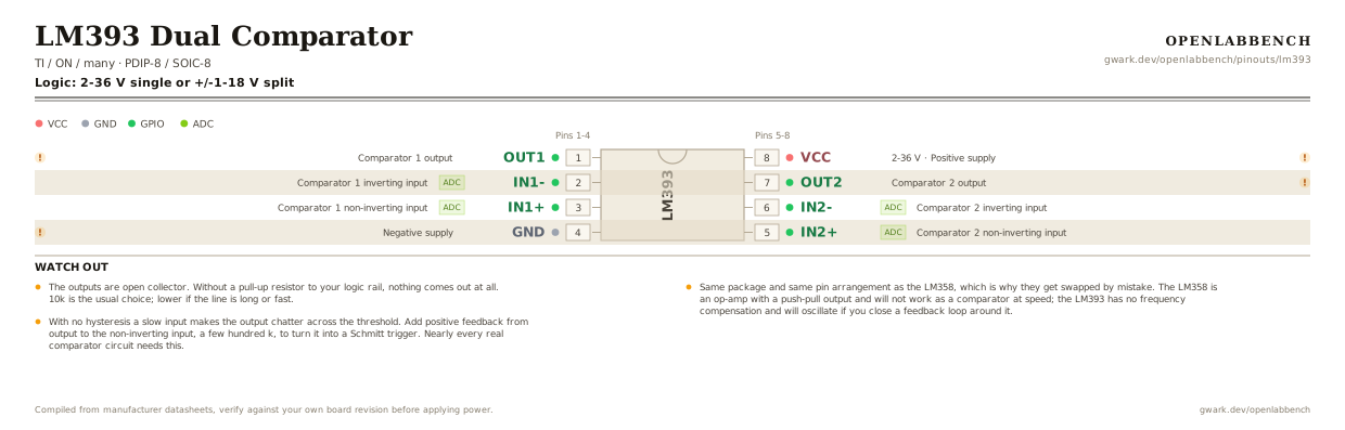
Fig. 1. LM393 Dual Comparator, PDIP-8. Hover or tap a signal to light up every pin that carries it.
2.Watch out
- The outputs are open collector. Without a pull-up resistor to your logic rail, nothing comes out at all. 10k is the usual choice; lower if the line is long or fast.
- Same package and same pin arrangement as the LM358, which is why they get swapped by mistake. The LM358 is an op-amp with a push-pull output and will not work as a comparator at speed; the LM393 has no frequency compensation and will oscillate if you close a feedback loop around it.
- With no hysteresis a slow input makes the output chatter across the threshold. Add positive feedback from output to the non-inverting input, a few hundred k, to turn it into a Schmitt trigger. Nearly every real comparator circuit needs this.
- Open collector means you can wire several outputs together on one pull-up and get a wired-AND, which is how multi-channel alarm circuits are built.
- Input common mode range goes down to ground but stops about 1.5 V below V+, the same limitation as the LM358.
- The LM339 is four of these in a DIP-14, at the cost of a different pinout.
3.Comparator with hysteresis
What has to go around the chip before it will run.
| Part | Between | Why |
|---|---|---|
| 10 kOhm | OUT1 (1) to VCC | The output is an open collector. It can only pull low, so without this there is no high level at all. |
| 1 MOhmoptional | OUT1 (1) to IN1+ (3) | Positive feedback. A few millivolts of hysteresis stops the output chattering as the inputs cross. |
| 100 nF | VCC (8) to GND | Supply decoupling at the pin. |
Open collector cuts both ways: it is why you can wire several outputs together as an AND, and why a comparator with no pull-up looks dead on a scope.
4.Full pin reference
Every pin, alias and mapping. This is the table that prints.
Table 2. Pin assignments.
| Pin | Name | Also called | Functions | Notes |
|---|---|---|---|---|
| 1 | OUT1 | OUTA | Comparator 1 output | Open collector. Needs a pull-up. |
| 2 | IN1-ADC | INA- | Comparator 1 inverting input | |
| 3 | IN1+ADC | INA+ | Comparator 1 non-inverting input | |
| 4 | GND | V- | Negative supply | Ground in a single supply circuit. |
| 5 | IN2+ADC | INB+ | Comparator 2 non-inverting input | |
| 6 | IN2-ADC | INB- | Comparator 2 inverting input | |
| 7 | OUT2 | OUTB | Comparator 2 output | Open collector. Needs a pull-up. |
| 8 | VCC2-36 V | - | Positive supply | 100 nF to ground at the pin. |
Primary sources
Found a wrong pin? The whole board is one file, data/boards/lm393.json.