Maxim / Analog Devices · Integrated circuit
MAX6675 Thermocouple Converter
Reads a type-K thermocouple to 1024 C and hands back a 12-bit number over SPI, with cold-junction compensation already done.
- Logic level
- 3-5.5 V
- Package
- SO-8
1.Pinout diagram
Highlight a signalhover to preview, click to keep
Pins 1-4
Pins 5-8
Pin detail
Hover a pin for its mappings and gotchas. Click to keep it here.
- Logic level
- 3-5.5 V
- Package
- SO-8
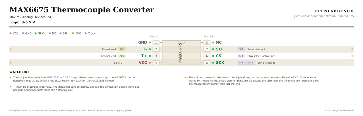
Fig. 1. MAX6675 Thermocouple Converter, SO-8. Hover or tap a signal to light up every pin that carries it.
2.Watch out
- The hot junction reads 0 to 1023.75 C in 0.25 C steps. Below zero it cannot go: the MAX6675 has no negative range at all, which is the usual reason to reach for the MAX31855 instead.
- The cold end, meaning the board the chip is sitting on, has to stay between -20 and +85 C. Compensation works by measuring the chip's own temperature, so putting the chip near the thing you are heating breaks the measurement rather than just the chip.
- T- must be grounded externally. The datasheet says so plainly, and it is the connection people leave out because a thermocouple looks like a floating pair.
- It is read-only SPI: there is no MOSI and nothing to configure. Drop CS low and clock out 16 bits. Bit 2 of that word is the open-thermocouple flag, which reads high when the probe is disconnected, and is worth checking because a missing probe otherwise looks like a plausible temperature.
- Type-K only. The linearization is built for that alloy pair, so a J, T or N probe will read, and will read wrong.
- Conversion takes about 0.2 s. Reading faster than that just returns the same number.
- Pin 8 is not connected. Modules usually bring it out anyway.
3.Minimum circuit
What has to go around the chip before it will run.
| Part | Between | Why |
|---|---|---|
| 0.1 uF ceramic | VCC (4) to GND | Supply bypass, called for by name in the datasheet's own pin description. The cold-junction sensor is on this rail. |
| Ground link | T- (2) to GND | T- has to be grounded externally. Left floating, the input pair has no common-mode reference and the reading wanders. |
| Type-K thermocouple | T+ (3) to T- (2) | Chromel to T+, alumel to T-. Reverse them and the temperature moves the wrong way as it heats. |
Nothing else is needed. CS, SCK and SO go straight to the microcontroller, and the chip has no registers to set up. For long probe leads a 10 nF across T+ and T- is the usual noise fix.
4.Full pin reference
Every pin, alias and mapping. This is the table that prints.
Table 2. Pin assignments.
| Pin | Name | Also called | Functions | Notes |
|---|---|---|---|---|
| 1 | GND | - | - | |
| 2 | T-ADC | - | Alumel lead | Connect to ground externally. This is not optional. |
| 3 | T+ADC | - | Chromel lead | |
| 4 | VCC3-5.5 V | - | - | Bypass with 0.1 uF to GND. |
| 5 | SCKSPIClock | - | Serial clock in | |
| 6 | CSSPI | /CS | Chip select, active low | Low enables the interface and starts shifting out the latest conversion. |
| 7 | SOSPI | MISO | Serial data out | Read only. There is no data input. |
| 8 | NC | - | - |
Looking for a substitute?
Primary sources
Found a wrong pin? The whole board is one file, data/boards/max6675.json.