Analog Devices (Maxim) · Integrated circuit
MAX7219 LED Display Driver
Drives eight 7-segment digits or an 8x8 matrix over three wires, with its own BCD decoder, brightness control and scanning. No refresh code at all.
- Logic level
- 4.0-5.5 V
- Package
- PDIP-24 / SOIC-24
1.Pinout diagram
Highlight a signalhover to preview, click to keep
Pins 1-12
MAX7219
Pins 13-24
Pin detail
Hover a pin for its mappings and gotchas. Click to keep it here.
- Logic level
- 4.0-5.5 V
- Package
- PDIP-24 / SOIC-24
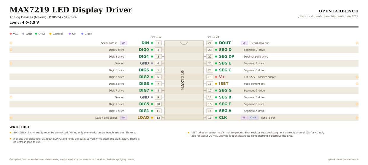
Fig. 1. MAX7219 LED Display Driver, PDIP-24. Hover or tap a signal to light up every pin that carries it.
2.Watch out
- Both GND pins, 4 and 9, must be connected. Wiring only one works on the bench and then flickers.
- ISET takes a resistor to V+, not to ground. That resistor sets peak segment current: around 10k for 40 mA, 28k for about 20 mA. Leaving it open means no light; shorting it destroys the chip.
- It scans the digits itself at about 800 Hz and holds the data, so you write once and walk away. There is no refresh loop to run.
- The digit and segment pins are scattered around the package in no sensible order. A matrix wired by eye instead of by pin number comes out transposed or mirrored, which is the single most common MAX7219 complaint.
- Brightness is both digital, 16 steps over SPI, and analog through ISET. Set the coarse level with the resistor and trim in software.
- Decode mode turns raw segment control into BCD digits per position. Turn it off for a matrix or for custom glyphs, on for numeric displays.
- The MAX7221 is the same part with SPI-compliant timing and slew-limited segment drivers for less RFI. It also respects CS properly, which matters on a shared bus.
- Peak current across all eight digits can reach 330 mA. The cheap modules do not decouple well; add 100 uF if the display dims as digits light.
3.Minimum circuit
What has to go around the chip before it will run.
| Part | Between | Why |
|---|---|---|
| 12 kOhm | ISET (18) to VCC | RSET sets the peak segment current, about 100 times the ISET current. Table 11 of the datasheet gives 11.8 kOhm for 40 mA into a 2 V LED. |
| 10 uF | V+ (19) to GND | The datasheet asks for this next to the part. Scanning digits pull current in hard bursts. |
| 100 nF | V+ (19) to GND | The ceramic half of the same job, as close to the pin as it will go. |
Both GND pins, 4 and 9, must be connected. 40 mA per segment is the recommended maximum; above that you need external digit drivers.
4.Full pin reference
Every pin, alias and mapping. This is the table that prints.
Table 2. Pin assignments.
| Pin | Name | Also called | Functions | Notes |
|---|---|---|---|---|
| 1 | DINSPI | - | Serial data in | This is MOSI. Sampled on the rising edge of CLK. |
| 2 | DIG0 | - | Digit 0 drive | Digit drivers are scattered across the package in no useful order. Wire from the numbers. |
| 3 | DIG4 | - | Digit 4 drive | |
| 4 | GND | - | Ground | Both ground pins, 4 and 9, must be connected. One is not enough. |
| 5 | DIG6 | - | Digit 6 drive | |
| 6 | DIG2 | - | Digit 2 drive | |
| 7 | DIG3 | - | Digit 3 drive | |
| 8 | DIG7 | - | Digit 7 drive | |
| 9 | GND | - | Ground | The second ground. Connect it. |
| 10 | DIG5 | - | Digit 5 drive | |
| 11 | DIG1 | - | Digit 1 drive | |
| 12 | LOADSPI | CS, /CS | Load / chip select | Rising edge latches the last 16 bits. This is CS. |
| 13 | CLKSPIClock | - | Serial clock | 10 MHz maximum. This is SCK. |
| 14 | SEG A | - | Segment A drive | |
| 15 | SEG F | - | Segment F drive | Segment order on the package is scrambled too: A, F, B, G down this side. |
| 16 | SEG B | - | Segment B drive | |
| 17 | SEG G | - | Segment G drive | |
| 18 | ISET | - | Peak current set | A resistor from here to V+ sets segment current. 10k gives roughly 40 mA per segment; never leave it open or short it. |
| 19 | V+4.0-5.5 V | - | Positive supply | 5 V. Needs 10 uF and 100 nF right at the pin; eight digits strobing is a hard load. |
| 20 | SEG C | - | Segment C drive | |
| 21 | SEG E | - | Segment E drive | |
| 22 | SEG DP | DP | Decimal point drive | |
| 23 | SEG D | - | Segment D drive | |
| 24 | DOUTSPI | - | Serial data out | Feed into the next chip's DIN to chain displays. Data appears 16.5 clocks later. |
Looking for a substitute?
Primary sources
Found a wrong pin? The whole board is one file, data/boards/max7219.json.