Milk-V · Single-board computer
Milk-V Duo (CV1800B)
A five dollar board that boots Linux on a RISC-V core, in the Raspberry Pi Pico footprint. USB-C at the top, pin 1 top-left.
- Logic level
- 3.3 V GPIO, 1.8 V ADC
- Package
- 2x20 castellated / 2.54 mm, 21 x 51 mm
1.Pinout diagram
Highlight a signalhover to preview, click to keep
Pins 1-20
MILK-V DUO
Pins 21-40
Pin detail
Hover a pin for its mappings and gotchas. Click to keep it here.
- Logic level
- 3.3 V GPIO, 1.8 V ADC
- Package
- 2x20 castellated / 2.54 mm, 21 x 51 mm
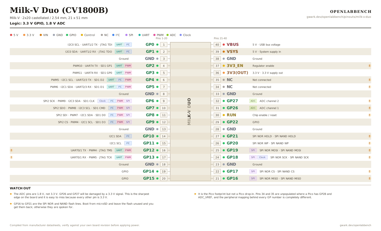
Fig. 1. Milk-V Duo (CV1800B), 2x20 castellated. Hover or tap a signal to light up every pin that carries it.
2.Watch out
- The ADC pins are 1.8 V, not 3.3 V. GP26 and GP27 will be damaged by a 3.3 V signal. This is the sharpest edge on the board and it is easy to miss because every other pin is 3.3 V.
- It is the Pico footprint but not a Pico drop-in. Pins 34 and 35 are unpopulated where a Pico has GP28 and ADC_VREF, and the peripheral mapping behind every GP number is completely different.
- GP16 to GP21 are the SPI NOR and NAND flash lines. Boot from microSD and leave the flash unused and you get them back; otherwise they are spoken for.
- There is 100 Mbps Ethernet on five pads along the bottom edge: TX+, TX-, GND, RX+, RX-. They need an external magnetics module or an RJ45 jack with magnetics built in.
- The serial console is UART0 on GP12 and GP13 at 3.3 V. With no display output, that console is how you talk to the board before networking comes up.
- It boots from microSD. There is no on-board eMMC on the base Duo, so the card is not optional.
- The CV1800B pairs a 1 GHz C906 RISC-V core with a 700 MHz one and a small 8051, and there is a camera socket on board. The later Duo 256M and Duo S use the SG2002 and change both the memory and some pin functions.
- GPIO numbers in sysfs are the XGPIO and PWR_GPIO values listed per pin, not the GP number on the silkscreen. GP0 is 508, not 0.
3.Full pin reference
Every pin, alias and mapping. This is the table that prints.
Table 1. Pin assignments.
| Pin | Name | Also called | Functions | Notes |
|---|---|---|---|---|
| 1 | GP0I²CUART | XGPIOA[28], 508 | I2C0 SCL, UART1/2 TX, JTAG TDI | |
| 2 | GP1I²CUART | XGPIOA[29], 509 | I2C0 SDA, UART1/2 RX, JTAG TDO | |
| 3 | GND | - | Ground | |
| 4 | GP2PWMUART | PWR_GPIO[26], 378 | PWM10, UART4 TX, SD1 GP1 | |
| 5 | GP3PWMUART | PWR_GPIO[25], 377 | PWM11, UART4 RX, SD1 GP0 | |
| 6 | GP4PWMI²CUART | PWR_GPIO[19], 371 | PWM5, I2C1 SCL, UART2/3 TX, SD1 D2 | |
| 7 | GP5PWMI²CUART | PWR_GPIO[20], 372 | PWM6, I2C1 SDA, UART2/3 RX, SD1 D1 | |
| 8 | GND | - | Ground | |
| 9 | GP6SPIPWMI²CClock | PWR_GPIO[23], 375 | SPI2 SCK, PWM9, I2C3 SDA, SD1 CLK | |
| 10 | GP7SPIPWMI²C | PWR_GPIO[22], 374 | SPI2 SDO, PWM8, I2C3 SCL, SD1 CMD | |
| 11 | GP8SPIPWMI²C | PWR_GPIO[21], 373 | SPI2 SDI, PWM7, I2C1 SDA, SD1 D0 | |
| 12 | GP9SPIPWMI²C | PWR_GPIO[18], 370 | SPI2 CS, PWM4, I2C1 SCL, SD1 D3 | |
| 13 | GND | - | Ground | |
| 14 | GP10I²C | XGPIOC[9], 425 | I2C1 SDA | |
| 15 | GP11I²C | XGPIOC[10], 426 | I2C1 SCL | |
| 16 | GP12PWMUART | XGPIOA[16], 496 | UART0/1 TX, PWM4, JTAG TMS | UART0 is the serial console by default, at 3.3 V. |
| 17 | GP13PWMUART | XGPIOA[17], 497 | UART0/1 RX, PWM5, JTAG TCK | The other half of the console. |
| 18 | GND | - | Ground | |
| 19 | GP14 | XGPIOA[14], 494 | GPIO | |
| 20 | GP15 | XGPIOA[15], 495 | GPIO | |
| 21 | GP16SPI | XGPIOA[23], 503 | SPI NOR MISO, SPI NAND MISO | Wired to the on-board SPI NOR / NAND flash. Free only if you boot from microSD and leave the flash alone. |
| 22 | GP17SPI | XGPIOA[24], 504 | SPI NOR CS, SPI NAND CS | Wired to the on-board SPI NOR / NAND flash. Free only if you boot from microSD and leave the flash alone. |
| 23 | GND | - | Ground | |
| 24 | GP18SPIClock | XGPIOA[22], 502 | SPI NOR SCK, SPI NAND SCK | Wired to the on-board SPI NOR / NAND flash. Free only if you boot from microSD and leave the flash alone. |
| 25 | GP19SPI | XGPIOA[25], 505 | SPI NOR MOSI, SPI NAND MOSI | Wired to the on-board SPI NOR / NAND flash. Free only if you boot from microSD and leave the flash alone. |
| 26 | GP20 | XGPIOA[27], 507 | SPI NOR WP, SPI NAND WP | Wired to the on-board SPI NOR / NAND flash. Free only if you boot from microSD and leave the flash alone. |
| 27 | GP21 | XGPIOA[26], 506 | SPI NOR HOLD, SPI NAND HOLD | Wired to the on-board SPI NOR / NAND flash. Free only if you boot from microSD and leave the flash alone. |
| 28 | GND | - | Ground | |
| 29 | GP22 | PWR_GPIO[4], 356 | GPIO | |
| 30 | RUN | RESET | Chip enable / reset | Pull low to reset, same position as the Pico's RUN pin. |
| 31 | GP26ADC | XGPIOB[3], 451, ADC1 | ADC channel 1 | 1.8 V MAXIMUM, not 3.3 V. Feeding it a 3.3 V signal damages the input. Divide everything. |
| 32 | GP27ADC | XGPIOB[6], 454, ADC2 | ADC channel 2 | 1.8 V MAXIMUM, not 3.3 V. |
| 33 | GND | - | Ground | |
| 34 | NC | - | Not connected | Unpopulated. The Pico has GP28 here, which is why a Pico carrier does not map one to one. |
| 35 | NC | - | Not connected | Unpopulated. The Pico has ADC_VREF here. |
| 36 | 3V3(OUT)3.3 V | - | 3.3 V supply out | |
| 37 | 3V3_EN | - | Regulator enable | Pulled high on board. Pull low to shut the 3.3 V rail down. |
| 38 | GND | - | Ground | |
| 39 | VSYS5 V | - | System supply in | |
| 40 | VBUS5 V | - | USB bus voltage |
Primary sources
Found a wrong pin? The whole board is one file, data/boards/milk-v-duo.json.