SparkFun / clones · Dev board
Pro Micro (ATmega32U4)
ATmega32U4 with native USB, so it can be a keyboard or a mouse without a helper chip. The board in most custom keyboard builds. USB at the top.
- Logic level
- 5 V at 16 MHz, or 3.3 V at 8 MHz
- Package
- 2x12 2.54 mm, 33 x 18 mm
1.Pinout diagram
Highlight a signalhover to preview, click to keep
Left (USB at top)
PRO MICRO
Right (USB at top)
Pin detail
Hover a pin for its mappings and gotchas. Click to keep it here.
- Logic level
- 5 V at 16 MHz, or 3.3 V at 8 MHz
- Package
- 2x12 2.54 mm, 33 x 18 mm
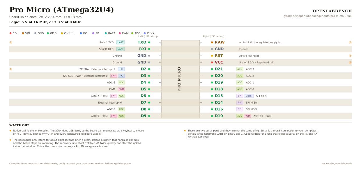
Fig. 1. Pro Micro (ATmega32U4), 2x12 2.54 mm, 33 x 18 mm. Hover or tap a signal to light up every pin that carries it.
2.Watch out
- Native USB is the whole point. The 32U4 does USB itself, so the board can enumerate as a keyboard, mouse or MIDI device. That is why QMK and every handwired keyboard uses it.
- There are two serial ports and they are not the same thing. Serial is the USB connection to your computer; Serial1 is the hardware UART on pins 0 and 1. Code written for a Uno that expects Serial on the TX and RX pins will not work.
- The bootloader only listens for about eight seconds after a reset. Upload a sketch that hangs or kills USB and the board stops enumerating. The recovery is to short RST to GND twice quickly and start the upload inside that window. This is the most common way a Pro Micro appears bricked.
- There is a 5 V 16 MHz version and a 3.3 V 8 MHz version, and they look identical. Picking the wrong board in the IDE sets the wrong fuses and the result is a board that no longer enumerates.
- RAW is the unregulated input, up to 12 V, feeding the on-board regulator. VCC is the regulated rail, and it is an output when the board is powered from RAW or USB. Feeding VCC directly bypasses the regulator.
- The analog pins are not where a Uno user expects. There is no A4 or A5. The ADC lives on A0 to A3 (pins 18 to 21) and A6 to A10 (pins 4, 6, 8, 9, 10).
- I2C is on pins 2 and 3, not on the analog pins.
- The micro-USB connector on the cheap clones is held on by solder pads alone and tears off. Glue it, or buy a USB-C clone.
3.Full pin reference
Every pin, alias and mapping. This is the table that prints.
Table 1. Pin assignments.
| Pin | Name | Also called | Functions | Notes |
|---|---|---|---|---|
| - | TXOUART | D1, TX, PD3 | Serial1 TXD | Hardware UART, not the USB serial. Use Serial1 in code. |
| - | RXIUART | D0, RX, PD2 | Serial1 RXD | |
| - | GND | - | Ground | |
| - | GND | - | Ground | |
| - | D2I²C | SDA, PD1 | I2C SDA, External interrupt 1 | I2C is here, not on the analog pins like a Uno. |
| - | D3I²CPWM | SCL, PD0 | I2C SCL, PWM, External interrupt 0 | |
| - | D4ADC | A6, PD4 | ADC 6 | |
| - | D5PWM | PC6 | PWM | |
| - | D6ADCPWM | A7, PD7 | ADC 7, PWM | |
| - | D7 | PE6 | External interrupt 6 | |
| - | D8ADC | A8, PB4 | ADC 8 | |
| - | D9ADCPWM | A9, PB5 | ADC 9, PWM | |
| - | RAWup to 12 V | - | Unregulated supply in | Feeds the on-board regulator. About 4.8 V when running from USB. |
| - | GND | - | Ground | |
| - | RST | - | Active-low reset | Short to GND twice quickly to force the bootloader. This is how you recover a board that stopped enumerating. |
| - | VCC5 V or 3.3 V | - | Regulated rail | An output when powered from RAW or USB. Driving it directly bypasses the regulator. |
| - | D21ADC | A3, PF4 | ADC 3 | |
| - | D20ADC | A2, PF5 | ADC 2 | |
| - | D19ADC | A1, PF6 | ADC 1 | |
| - | D18ADC | A0, PF7 | ADC 0 | |
| - | D15SPIClock | SCLK, SCK, PB1 | SPI clock | |
| - | D14SPI | MISO, PB3 | SPI MISO | |
| - | D16SPI | MOSI, PB2 | SPI MOSI | |
| - | D10ADCPWM | A10, PB6 | ADC 10, PWM |
Primary sources
Found a wrong pin? The whole board is one file, data/boards/pro-micro-32u4.json.