TI / Nexperia / many · Integrated circuit
74HC08 Quad AND Gate
Four 2-input AND gates. Same pin arrangement as the 74HC00, so the two get mixed up constantly.
- Logic level
- 2-6 V (HC)
- Package
- PDIP-14 / SOIC-14
1.Pinout diagram
Highlight a signalhover to preview, click to keep
Pins 1-7
74HC08
Pins 8-14
Pin detail
Hover a pin for its mappings and gotchas. Click to keep it here.
- Logic level
- 2-6 V (HC)
- Package
- PDIP-14 / SOIC-14
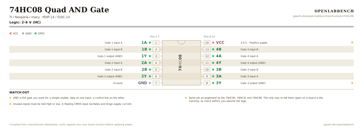
Fig. 1. 74HC08 Quad AND Gate, PDIP-14. Hover or tap a signal to light up every pin that carries it.
2.Watch out
- AND is the gate you want for a simple enable: data on one input, a control line on the other.
- Same pin arrangement as the 74HC00, 74HC32 and 74HC86. The only way to tell them apart on a board is the marking, so check before you assume the logic.
- Unused inputs must be tied high or low. A floating CMOS input oscillates and drags supply current.
- HC inputs need a level near their own rail. Driving a 5 V part from 3.3 V logic wants the HCT version.
3.Minimum circuit
What has to go around the chip before it will run.
| Part | Between | Why |
|---|---|---|
| Wire link | 1B (2) to VCC | One input high turns the gate into a plain buffer for the other. The usual way a spare AND gets used. |
| Wire link | 4A (12) to GND | An unused input cannot be left floating: a CMOS input at mid-rail turns both transistors on and the chip heats up. |
| Wire link | 4B (13) to GND | The other input of the same unused gate. Tie every one of them, not just one per gate. |
| 100 nF | VCC (14) to GND | Supply decoupling at the pin. |
Unused inputs are the one thing people skip on a 74HC part and the one thing that produces a warm chip, random outputs and an oscillation nobody can find.
4.Full pin reference
Every pin, alias and mapping. This is the table that prints.
Table 2. Pin assignments.
| Pin | Name | Also called | Functions | Notes |
|---|---|---|---|---|
| 1 | 1A | - | Gate 1 input A | |
| 2 | 1B | - | Gate 1 input B | |
| 3 | 1Y | - | Gate 1 output (AND) | |
| 4 | 2A | - | Gate 2 input A | |
| 5 | 2B | - | Gate 2 input B | |
| 6 | 2Y | - | Gate 2 output (AND) | |
| 7 | GND | - | Ground | |
| 8 | 3Y | - | Gate 3 output (AND) | Output comes first on this side. |
| 9 | 3A | - | Gate 3 input A | |
| 10 | 3B | - | Gate 3 input B | |
| 11 | 4Y | - | Gate 4 output (AND) | |
| 12 | 4A | - | Gate 4 input A | |
| 13 | 4B | - | Gate 4 input B | |
| 14 | VCC2-6 V | - | Positive supply | 100 nF at the pin. |
Primary sources
Found a wrong pin? The whole board is one file, data/boards/sn74hc08.json.