PJRC · Dev board
Teensy 4.0
600 MHz Cortex-M7 on a board the size of a postage stamp. Nothing else in the hobby space is close on raw speed. USB at the top.
- Logic level
- 3.3 V, not 5 V tolerant
- Package
- 2x14 2.54 mm, 35 x 18 mm
1.Pinout diagram
Highlight a signalhover to preview, click to keep
Left (USB at top)
TEENSY 4.0
Right (USB at top)
Pin detail
Hover a pin for its mappings and gotchas. Click to keep it here.
- Logic level
- 3.3 V, not 5 V tolerant
- Package
- 2x14 2.54 mm, 35 x 18 mm
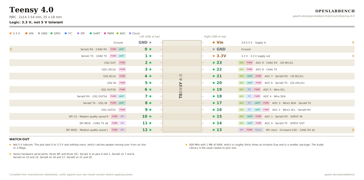
Fig. 1. Teensy 4.0, 2x14 2.54 mm, 35 x 18 mm. Hover or tap a signal to light up every pin that carries it.
2.Watch out
- Not 5 V tolerant. The pins take 0 to 3.3 V and nothing more, which catches people moving over from an Uno or a Mega.
- 600 MHz with 1 MB of RAM, which is roughly thirty times an Arduino Due and in a smaller package. The Audio Library is the usual reason to pick one.
- Seven hardware serial ports, three SPI and three I2C. Serial1 is on pins 0 and 1, Serial2 on 7 and 8, Serial3 on 15 and 14, Serial4 on 16 and 17, Serial5 on 21 and 20.
- Wire is on pins 18 and 19, Wire1 on 17 and 16. The second I2C bus shares pins with Serial4, so you get one or the other.
- Pin 13 is the on-board LED and the SPI clock at once. PJRC warn against INPUT_PULLUP on it.
- Vin accepts 3.6 to 5.5 V, and the 3.3 V output is good for 250 mA. To run from an external supply with USB also plugged in, cut the VUSB pad on the underside first.
- Another sixteen pads sit on the underside for pins 24 to 39, plus five on the back edge for program, on/off, ground and VBat. Those are not on this diagram.
- Every digital pin can raise an interrupt and 31 of them do PWM, so the usual hunt for a free interrupt or timer pin does not apply here.
- The Teensy 4.1 is the longer version of the same chip, adding Ethernet, a microSD slot, a USB host port and 55 I/O.
3.Full pin reference
Every pin, alias and mapping. This is the table that prints.
Table 1. Pin assignments.
| Pin | Name | Also called | Functions | Notes |
|---|---|---|---|---|
| - | GND | - | Ground | |
| - | 0UARTPWM | RX1, CRX2 | Serial1 RX, CAN2 RX | Serial1 RX and CAN2 RX. Not printed on the reference card's front. |
| - | 1UARTPWM | TX1, CTX2 | Serial1 TX, CAN2 TX | |
| - | 2PWM | OUT2 | I2S2 OUT | |
| - | 3PWM | LRCLK2 | I2S2 LRCLK | |
| - | 4PWM | BCLK2 | I2S2 BCLK | |
| - | 5PWM | IN2 | I2S2 IN | |
| - | 6PWM | OUT1D | I2S1 OUT1D | |
| - | 7UARTPWM | RX2, OUT1A | Serial2 RX, I2S1 OUT1A | |
| - | 8UARTPWM | TX2, IN1 | Serial2 TX, I2S1 IN | |
| - | 9PWM | OUT1C | I2S1 OUT1C | |
| - | 10SPIPWM | CS, MQSR | SPI CS, Medium quality sound R | |
| - | 11SPIPWM | MOSI, CTX1 | SPI MOSI, CAN1 TX alt | |
| - | 12SPIPWM | MISO, MQSL | SPI MISO, Medium quality sound L | |
| - | Vin3.6-5.5 V | - | Supply in | Cut the VUSB pad on the back before feeding this from an external supply while USB is also connected. |
| - | GND | - | Ground | |
| - | 3.3V3.3 V | - | 3.3 V supply out | 250 mA maximum. The regulator is small; a hungry peripheral needs its own. |
| - | 23ADCPWM | A9, CRX1 | ADC 9, CAN1 RX, I2S MCLK1 | |
| - | 22ADCPWM | A8, CTX1 | ADC 8, CAN1 TX | |
| - | 21ADCUARTPWM | A7, RX5 | ADC 7, Serial5 RX, I2S BCLK1 | |
| - | 20ADCUARTPWM | A6, TX5 | ADC 6, Serial5 TX, I2S LRCLK1 | |
| - | 19ADCI²CPWM | A5, SCL0 | ADC 5, Wire SCL | |
| - | 18ADCI²CPWM | A4, SDA0 | ADC 4, Wire SDA | |
| - | 17ADCI²CUARTPWM | A3, SDA1, TX4 | ADC 3, Wire1 SDA, Serial4 TX | |
| - | 16ADCI²CUARTPWM | A2, SCL1, RX4 | ADC 2, Wire1 SCL, Serial4 RX | |
| - | 15ADCUARTPWM | A1, RX3 | ADC 1, Serial3 RX, S/PDIF IN | |
| - | 14ADCUARTPWM | A0, TX3 | ADC 0, Serial3 TX, S/PDIF OUT | |
| - | 13SPIPWMClock | LED, SCK, CRX1 | SPI clock, On-board LED, CAN1 RX alt | On-board orange LED. Do not use INPUT_PULLUP on this pin. |
Primary sources
Found a wrong pin? The whole board is one file, data/boards/teensy-4-0.json.