NanJing Top Power ASIC · Integrated circuit
TP4056 Li-Ion Charger
A complete single-cell lithium charger in eight pins. One resistor sets the current, and nothing else is needed, which is why it is on every USB charging module sold.
- Logic level
- 4-8 V in, 4.2 V out
- Package
- SOP-8
1.Pinout diagram
Highlight a signalhover to preview, click to keep
Pins 1-4
Pins 5-8
Pin detail
Hover a pin for its mappings and gotchas. Click to keep it here.
- Logic level
- 4-8 V in, 4.2 V out
- Package
- SOP-8
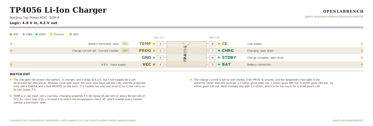
Fig. 1. TP4056 Li-Ion Charger, SOP-8. Hover or tap a signal to light up every pin that carries it.
2.Watch out
- The chip does not protect the battery. It charges, and it stops at 4.2 V, but it will happily let a cell be drained flat afterwards. Modules come both ways: the bare ones have just this chip, and the protected ones add a DW01A and a dual MOSFET on the back. If a module has only one small IC on it, the cell is on its own below 3 V.
- The charge current is set by one resistor from PROG to ground, and the datasheet's own table is the authority rather than the formula: 1.2 kOhm gives 1000 mA, 2 kOhm gives 580 mA, 5 kOhm gives 250 mA, 10 kOhm gives 130 mA. Most modules ship with 1.2 kOhm, which is far too much for a small pouch cell.
- TEMP is a real input, not a courtesy. Charging suspends if it sits below 45 percent or above 80 percent of VCC for more than 0.15 s. Ground it to switch the temperature check off, which is what every module without a thermistor does.
- CHRG and STDBY are open-drain outputs, low when active. They are what the two LEDs on a module hang off, through about 1 kOhm each.
- With a 10 uF capacitor on BAT and no battery connected, the red LED blinks every one to four seconds instead of settling. That is the documented no-battery behavior, not a fault.
- It is a linear charger, so everything between the input and 4.2 V turns into heat in the package. At 1 A from 5 V that is around a watt, and the chip will throttle itself back to hold 145 C junction temperature. Charging gets slower as it gets hotter, by design.
- VCC has to stay above the battery voltage. When the input falls to within 30 mV of BAT the chip sleeps and the battery stops being drained through it, under 2 uA.
3.Minimum circuit to charge a cell
What has to go around the chip before it will run.
| Part | Between | Why |
|---|---|---|
| 10 uF ceramic | VCC (4) to GND | Input bulk, from the datasheet's own application circuit. A USB cable is long enough to be an inductor. |
| 10 uF ceramic | BAT (5) to GND | Output bulk on the BAT pin, as drawn in the reference circuit. It also keeps the loop stable before a cell is attached. |
| 1.2 kOhm (RPROG) | PROG (2) to GND | Sets the charge current, here 1000 mA. Raise it for a smaller cell: 2 kOhm is 580 mA and 10 kOhm is 130 mA. |
| Enable link | CE (8) to VCC | CE high puts the chip in normal mode. Low disables it, so this is where a microcontroller would take control. |
| TEMP link | TEMP (1) to GND | Grounding TEMP disables the thermistor check. Without a cell that has an NTC, this is the only correct thing to do with the pin. |
| Li-ion cell | BAT (5) to GND | One cell, charged to a 4.2 V float. This pin regulates, so nothing else goes between the chip and the battery. |
| Red LED + 1 kOhmoptional | CHRG (7) to VCC | CHRG pulls low while charging, so the LED lights during charge and goes out when it finishes. |
| Green LED + 1 kOhmoptional | STDBY (6) to VCC | STDBY pulls low at charge termination, which is the done light. |
A thermistor in the battery pack goes to TEMP instead of the ground link, with its own divider to VCC. Nothing here protects the cell from over-discharge; that needs a separate protection circuit between the battery and the load.
4.Full pin reference
Every pin, alias and mapping. This is the table that prints.
Table 2. Pin assignments.
| Pin | Name | Also called | Functions | Notes |
|---|---|---|---|---|
| 1 | TEMPADC | - | Battery thermistor input | Charging suspends outside 45 to 80 percent of VCC. Ground it to disable. |
| 2 | PROGADC | - | Charge current set, Current monitor | Resistor to ground sets the current. The pin voltage also reports it: 2 V in constant-current mode. |
| 3 | GND | - | - | |
| 4 | VCC4-8 V | - | Input supply | Must stay above the battery voltage. Within 30 mV of BAT the chip sleeps. |
| 5 | BAT | - | Battery connection | Regulates to 4.2 V. Draws under 2 uA from the cell when disabled or asleep. |
| 6 | STDBY | /STDBY | Charge complete, open drain | Pulled low when charging has terminated. High impedance otherwise. |
| 7 | CHRG | /CHRG | Charging, open drain | Pulled low while charging. Blinks slowly when there is no battery. |
| 8 | CE | - | Chip enable | High for normal operation, low to disable. Takes TTL or CMOS levels. |
Looking for a substitute?
Primary sources
Found a wrong pin? The whole board is one file, data/boards/tp4056.json.