Worldsemi · Integrated circuit
WS2812B Addressable LED
RGB LED with the controller on the die. Four pins, one data wire, and more ways to go wrong than any other four-pin part.
- Logic level
- 5 V data, 0.7 x VDD threshold
- Package
- 5050 SMD, 4 pad
1.Pinout diagram
Highlight a signalhover to preview, click to keep
Pins 1-2
WS2812B
Pins 3-4
Pin detail
Hover a pin for its mappings and gotchas. Click to keep it here.
- Logic level
- 5 V data, 0.7 x VDD threshold
- Package
- 5050 SMD, 4 pad
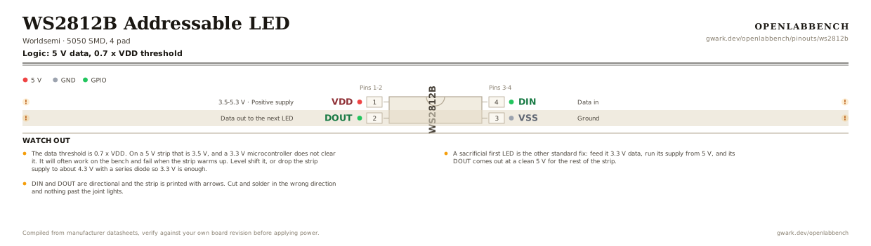
Fig. 1. WS2812B Addressable LED, 5050 SMD, 4 pad. Hover or tap a signal to light up every pin that carries it.
2.Watch out
- The data threshold is 0.7 x VDD. On a 5 V strip that is 3.5 V, and a 3.3 V microcontroller does not clear it. It will often work on the bench and fail when the strip warms up. Level shift it, or drop the strip supply to about 4.3 V with a series diode so 3.3 V is enough.
- A sacrificial first LED is the other standard fix: feed it 3.3 V data, run its supply from 5 V, and its DOUT comes out at a clean 5 V for the rest of the strip.
- DIN and DOUT are directional and the strip is printed with arrows. Cut and solder in the wrong direction and nothing past the joint lights.
- 60 mA per LED at full white. A 1 m 60-LED strip is 3.6 A, which is far beyond any dev board's 5 V pin. Feed the strip directly and tie the grounds together.
- 300 to 500 ohm in series with DIN and 1000 uF across the supply at the head of the strip. Both are in the datasheet and both are usually skipped.
- Long runs need power injected every meter or so, or the far end turns brown-red as the supply sags.
- Bit timing is about 1.25 us and has no clock to resynchronize to, so an interrupt mid-frame corrupts the rest of the strip. On AVR that means interrupts off during a write; on RP2040 use PIO and on ESP32 use RMT.
- SK6812 is the usual second source and adds an RGBW variant. WS2815 runs on 12 V with a backup data line so one dead LED does not kill the rest of the run.
3.Driving a strip
What has to go around the chip before it will run.
| Part | Between | Why |
|---|---|---|
| 300 to 500 Ohm | MCU to DIN (4) | In series with the controller's data output. Damps the edge and protects the first LED's input. |
| 1000 uF | VDD (1) to GND | Absorbs the inrush when the whole strip lights at once. |
| 100 nFoptional | VDD (1) to GND | Per LED, already on a finished strip. Only relevant if you lay out your own board. |
Data must clear 0.7 x VDD. From a 3.3 V controller into a 5 V strip it does not, so level shift, drop the strip supply with a series diode, or sacrifice the first LED as a shifter.
4.Full pin reference
Every pin, alias and mapping. This is the table that prints.
Table 2. Pin assignments.
| Pin | Name | Also called | Functions | Notes |
|---|---|---|---|---|
| 1 | VDD3.5-5.3 V | - | Positive supply | 100 nF per LED, and 1000 uF bulk at the head of the strip. |
| 2 | DOUT | - | Data out to the next LED | Reshaped 5 V output. This is what makes a sacrificial first pixel work as a level shifter. |
| 3 | VSS | GND | Ground | Must be common with the controller's ground, even when the strip has its own supply. |
| 4 | DIN | - | Data in | Needs 0.7 x VDD to register. 300 to 500 ohm in series here. |
Primary sources
Found a wrong pin? The whole board is one file, data/boards/ws2812b.json.